RBSE Solutions for Class 12 Physics Chapter 7 Alternating Current
Rajasthan Board RBSE Solutions for Class 12 Physics Chapter 7 Alternating Current Textbook Exercise Questions and Answers.
Rajasthan Board RBSE Solutions for Class 12 Physics in Hindi Medium & English Medium are part of RBSE Solutions for Class 12. Students can also read RBSE Class 12 Physics Important Questions for exam preparation. Students can also go through RBSE Class 12 Physics Notes to understand and remember the concepts easily. Browsing through wave optics important questions that include all questions presented in the textbook.
RBSE Class 12 Physics Solutions Chapter 7 Alternating Current
RBSE Class 12 Physics Alternating Current Textbook Questions and Answers
Question 7.1.
A 100 Ω resistor is connected to a 200 V, 50 Hz a.c. supply.
(a) What is the rms value of current in the circuit?
(b) What is the net power consumed over a full cycle?
Answer:
Given R = 100 Ω
E = 200 V
v = 50 Hz
(a) Since Iv = \(\frac{\mathrm{E}_v}{12}\)
So Iv = \(\frac{220}{100}\) = 2.2 A
(b) Pav = Ev Iv
= 220 x 2.2
or Pav = 484 W.

Question 7.2.
(a) The peak voltage of an ac supply is 300 V. What is the rms voltage?
(b) The rms value of current in an a.c. circuit is 10 A. What is the peak current?
Answer:
(a) Given E0 = 300 V, Ev = ?
Since Ev = \(\frac{\mathrm{E}_0}{\sqrt{2}}\) = 0.707 x 300
or Ev = 212.1 V
(b) Given Iv = 10 A, I0 = ?
Since I0 =\( \sqrt{2}\) Ev
= 1.414 x 10
or I = 14.14 A
Question 7.3.
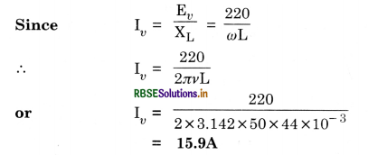
A 44 mH inductor is connected to 220V, 50Hz a.c. supply. Determine the rms value of the current in the circuit.
Answer:
Given L = 44 mH - 44 x 10-3 H
Ev = 220 V, v = 50 Hz
Iv =?
Question 7.4.
A 60 µF capacitor is connected to a 110V, 60 Hz a.c. supply. Determine the rms value of the current in the circuit.
Answer:
Given C = 60 µF = 60 x 10-6 F
Ev = 110 V, v = 60 Hz
Since Iv = \(\frac{\mathrm{E}_v}{\mathrm{X}_{\mathrm{C}}}\)
∴ Iv = ω C Ev = 2πv C Ev
= 2 x 3.142 x 60 x 60 x 10-6 x 110
= 2.49 A
or Iv = 2.49 A
Question 7.5.
In Exercises 7.3 and 7.4, what is the net power absorbed by each circuit over a complete cycle. Explain your answer.
Answer:
In both the cases the net power consumed is zero because in both the cases
Net power consumed
P = Ev Iv cos Φ
and Φ = 90°
∴ P = 0 (in each case)
Question 7.6.
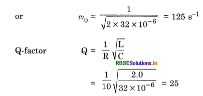
Obtain the resonant frequency ωr of a series LCR circuit with L = 2.0 H, C = 32 µF and R = 10 Ω. What is the Q - value of this circuit?
Answer:
Given L = 2.0 H
C = 32 µF = 32 x 10-6 F
R = 10 Ω, Q = ?, ω0 = ?
Resonant frequency
ω0 = \(\frac{1}{\sqrt{\mathrm{LC}}}\)
Question 7.7.
A charged 30 µF, capacitor is connected to a 27 mH inductor. What is the angular frequency of free oscillations of the circuit?
Answer:
Given C = 30 µF = 30 x 10-6 F
L = 27 mH = 27 x 10-3 H
ω0 = ?
ω0 = \(\frac{1}{\sqrt{\mathrm{LC}}}=\frac{1}{\sqrt{30 \times 10^{-6} \times 27 \times 10^{-3}}}\)
or ω0 = 1.1 x 10⁻³ s-1
Question 7.8.
Suppose the initial charge on the capacitor in Exercise 7.7 is 6 mC. What is the total energy stored in the circuit initially? What is the total energy at later time?
Answer:
Given q0 = 6mC = 6 x 10⁻³ C
∴Energy stored initially is given by
U0 = \(\frac{q_0^2}{2 \mathrm{C}}=\frac{36 \times 10^{-6}}{2 \times 30 \times 10^{-6}}\) = 0.6 J
At later time energy remains constant i.e. 0.6 J
Question 7.9.
A series LCR circuit with R = 20 Ω, L = 1.5 H and C = 35 µF is connected to a variable frequency 200 V a.c. supply. When the frequency of the supply equals the natural frequency of the circuit, what is the average power transferred to the circuit in one complete cycle?
Answer:
Given R = 20 Ω, L = 1.5 H,
C = 35 µF = 35 x 10-6 F
Ev = 200
When frequency of supply equals the natural frequency of the circuit, we get resonance condition.
∴ Z = R = 20 Ω
So Iv = \(\frac{\mathrm{E}_v}{\mathrm{Z}}=\frac{\mathrm{E}_v}{\mathrm{R}}=\frac{200}{20}\) = 10 A
And P = Ev Iv cos 0° = 200 x 10 x 1
or P = 2,000 W.
Question 7.10.
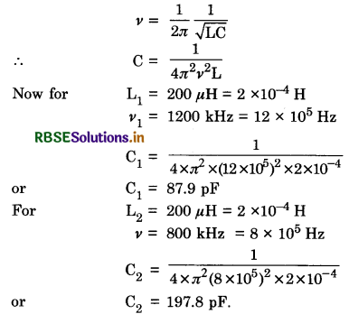
A radio can tune over the frequency range of a portion of MW broadcast band: (800 kHz to 1200 kHz). If its circuit has an effective inductance of 200 µH, what must be the range of its variable capacitor?
[Hint. For tuning, the natural frequency i.e. the frequency of free oscillations of the LC circuit should be equal to the frequency of the radio wave.]
Answer:
Since
Question 7.11.
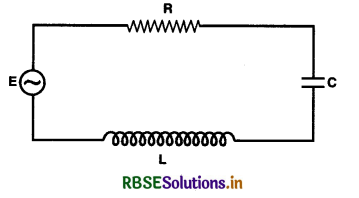
Figure TBQ 7.11 shows a series LCR circuit connected to a variable frequency 230 V source.
L = 5.0 H, C = 80 µF, R = 40 Ω
(a) Determine the source frequency which drives the circuit in resonance.
(b) Obtain the impedance of the circuit and the amplitude of current at the resonating frequency.
(c) Determine the rms potential drop across the three elements of the circuit. Show that the potential drop across the LC combination is zero at the resonating frequency.
Answer:
(a) Resonant frequency
ω0 = \(\frac{1}{\sqrt{\mathrm{LC}}}\)
= \(\frac{1}{\sqrt{5.0 \times 80 \times 10^{-6}}}\) = 50 rad s-1
(b) At resonance, ωL = \(\frac{1}{\omega \mathrm{C}}\)
∴ Impedance,
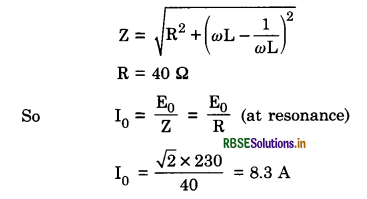
(c) Across L, Erms = Irms x ω0L
or Erms = \(\frac{230}{40}\) x 50 x 5 = 1437.5 V
Across C, Erms = Irms x \(\frac{1}{\omega_0 C}\)
= \(\frac{230}{40} \times \frac{1}{50 \times 80 \times 10^{-6}}\)
Total potential drop across L and C,
Erms = Irms x \(\left(\omega_0 \mathrm{~L}-\frac{1}{\omega_0 \mathrm{C}}\right)\)
or Erms = 1437.5 - 1437.5 = 0
Across R, Erms = \(\frac{230}{40}\) x 40 = 230 V.
ADDITIONAL EXERCISES
Question 7.12.
A LC circuit contains a 20 mH inductor and a 50 µF capacitor with an initial charge of 10 mC. The resistance of the circuit is negligible. Let the instant the circuit is closed be t = 0.
(a) What is the total energy stored initially? Is it conserved during the LC oscillations?
(b) What is the natural frequency of the circuit?
(c) At what time is the energy stored?
(i) completely magnetic (i.e. stored in the capacitor)?
(ii) completely magnetic (i.e. stored in the inductor)?
(d) At what times is the total energy shared equally between the inductor and the capacitor?
(e) If a resistor is inserted in the circuit, how much energy is eventually dissipated as heat?
Answer:
(a) L = 20 mH = 20 x 10-3 H
C = 50 µF = 50 x 10-6 F
q0 = 10 mC = 10-2 C
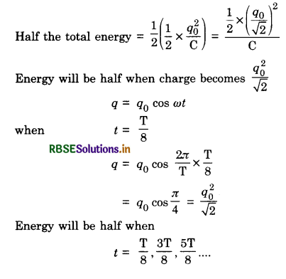
Total initial energy = \(\frac{1}{2} \frac{q_0^2}{\mathrm{C}}=\frac{1}{2} \times \frac{10^{-2} \times 10^{-2}}{50 \times 10^{-6}} \mathrm{~J}\)
= 1.0 J
Yes, sum of energies stored in L and C is conserved if R = 0.
(b) v = \(\frac{1}{2 \pi \sqrt{\mathrm{LC}}}\)
or λ = \(\frac{1}{2 \times 22 \sqrt{20 \times 10^{-3} \times 50 \times 10^{-2}}}\)
= 159.1 Hz
(c) (i) Charge on the capacitor at any instance
q = q0 cos ωt
q = q0 cos \(\frac{2 \pi}{\mathrm{T}}\) t
The charge and electrical energy will be the same when t = 0, \(\frac{\mathrm{T}}{2}\), T, \(\frac{\mathrm{3T}}{2}\) .............
(ii) Magnetic energy will be present when electric energy on the capacitor will be zero i.e. for
t = \(\frac{T}{4}, \frac{3 \mathrm{~T}}{4}, \frac{5 \mathrm{~T}}{4} \ldots\)
(d) Max, energy of capacitor = \(\frac{1}{2} \times \frac{q_0^2}{\mathrm{C}}\)
(e) R damps out the LC oscillations eventually.
The whole of the initial energy equal to 1.0 J is eventually dissipated as heat.
Question 7.13.
A coil of inductance 0.50 H and resistance 100 Ω is connected to a 240V, 50 Hz, a.c. supply.
(a) What is the maximum current in the coil?
(b) What is the time lag between the voltage maximum and current maximum?
Answer:
(a) For LR circuit.
L = 0.50 H, R = 100 Ω
or E0 = 240 V, v = 50 Hz
I0 = \(\frac{\mathrm{E}_0}{\sqrt{\mathrm{R}^2+\mathrm{L}^2 \omega^2}}=\frac{\mathrm{E}_0}{\sqrt{\mathrm{R}^2+\mathrm{L}^2}(2 \pi v)^2}\)
= \(\frac{\sqrt{2} \times 240}{\sqrt{10^4+(0.5)^2 \times 4 \pi^2 \times 2500}}\) =1.82 A.
(b) E is max. at t = 0, I is max. at t = \frac{\phi}{\omega}. If δ is positive, this means current maximum lags behind voltage maximum by a time = \(\frac{\phi}{\omega}\)
Now tan Φ = \(\frac{\omega \mathrm{L}}{\mathrm{R}}=\frac{2 \pi \times 20 \times 0.5}{100}\) = 1.571
or Φ = tan-1(1.571) ≈ 57.5°
Time lag = \(\frac{\phi}{\omega}=\frac{57.5 \pi}{180 \times 2 \pi \times 50}\) = 3.2 ms.
Question 7.14.
Obtain the answers (a) to (b) in Exercise 7.13 if the circuit is connected to high-frequency supply (240 V,10 kHz). Hence explain statement that at very high frequency, inductor in circuit nearly amounts to open circuit. How does an inductor behave in a d.c. circuit after the steady state?
Answer:
For the high frequency ω = 2π x 10-4 rad s-1
I0 = \(\frac{\sqrt{2} \times 240}{\sqrt{10^4+(0.5)^2 \times 4 \pi^2 \times 10^8}}\) = 1.1 x 10⁻² A
Term from R is negligible in the above denominator
tan Φ = \(\frac{2 \pi \times 10^4 \times 0.5}{100}\) = 100 π
Φ = 89°48' = 89.8° which is close to π/2 (i.e. 90°)
I0 is much smaller than for the low frequency in case of Q. 7.13 showing thereby that at high frequencies L nearly amounts to an open circuit. In a d.c. circuit (after steady state) ω = 0, so here L acts like a pure conductor.
Question 7.15.
A 100 µF capacitor in series with a 10 Q resistance is connected to a 110 V, 60 Hz supply.
(a) What is the maximum current in the circuit?
(b) What is the time lag between the current maximum and voltage maximum?
Answer:
For a C.R. circuit,
If E = E0 cos (ωt - Φ)
I = \(\frac{\mathrm{E}_0}{\sqrt{\mathrm{R}^2+\frac{1}{\omega^2 \mathrm{C}^2}}}\)
and tan Φ = -\(\frac{1}{\omega \mathrm{CR}}\)
(a) Max. current
Negative sign means that the current leads (i.e. voltage lags).
Question 7.16.
Obtain the answers to (a) and (b) in Exercise 7.15 if the circuit is connected to a 110 V,12 kHz supply? Hence explain the statement that a capacitor is a conductor at very high frequencies. Compare this behavior with that of a capacitor in a d.c. circuit after the steady state.
Answer:
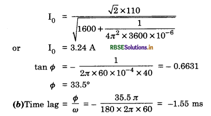
(a) I0 = \(\frac{\sqrt{2} \times 100}{\sqrt{1600+\frac{1}{4 \pi^2 \times 144 \times 10^6 \times 10^{-6}}}}\) = 3.9 A
Term for C is negligible at high frequency.
(b) tan Φ = -\(\frac{1}{2 \pi \times 12 \times 10^3 \times 10^{-4} \times 40}=-\frac{1}{96 \pi}\)
δ is nearly zero at high frequency. We see that at high frequencies C acts like a conductor. For a d.c. circuit after steady state, ω = 0 and C amounts to an open circuit.
Question 7.17.
Keeping the source frequency equal to the resonating frequency to the series LCR circuit, if the three elements L, C and R are arranged in parallel, shows that the total currents in the parallel LCR circuit is minimum at this frequency. Obtain the current rms value in each branch of the circuit for the elements and sources specified in exercise 7.11 for this frequency.
Answer:
Effective impedance of the parallel LCR is given by
i.e. \(\frac{1}{\mathrm{Z}}=\sqrt{\frac{1}{\mathrm{R}^2}+\left(\omega \mathrm{C}-\frac{1}{\omega \mathrm{L}}\right)^2}\)
which is minimum at ω = ω0 = \(\frac{1}{\sqrt{\mathrm{LC}}}\)
Therefore Z is maximum ω = ω0 and the total current amplitude is minimum.
In R branch,
Irms = \(\frac{\mathrm{I}_{r m s}}{\mathrm{R}}=\frac{230}{40}\) = 5.75 A
In L branch,
Irms = \(\frac{\mathrm{E}_{\mathrm{rms}}}{\omega_0 \mathrm{~L}}\)
Irms = \(\frac{230}{50 \times 5}\) = 0.92 A
In C branch, Irms = Erms x ω0C
= 230 x 50 x 80 x 10-6
= 0.92 A.
Question 7.18.
A circuit containing a 80 mH inductor and a 60 µF capacitor in series is connected to a 230 V, 50 Hz supply. The resistance in the circuit is negligible.
(a) Obtain the current amplitude and rms values.
(b) Obtain the rms values of potential drops across each element.
(c) What is the average power transferred to the inductor?
(d) What is the average power transferred to the capacitor?
(e) What is the total average power absorbed by the circuit? [‘Average’ implies ‘averaged over one cycle’.]
Answer:
(a) Here, L = 80 mH = 80 x 10-3H,
C = 60 µF = 60 x 10-6 F,
Erms = 230 V
v = 50 Hz, I0 = ?, Ir.m.s. = ?
Circuit impedance,
Z = ωL - \(\frac{1}{\omega C}\)
= 2 x π x 50 x 80 x 10-3 - \(\frac{1}{2 \times \pi \times 50 \times 60 \times 10^{-6}}\)
= 25.13 - 53.05 = 27.92 Ω
or Z ≃ -28 Ω
(-ve sign means reactance is capacitive)
Current amplitude,
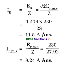
(b) Er.m.s = ωLIr.rm.s = 25.13 x 8.24
= 207.1V ≃ 207 V Ans.
(Ec )r.m.s = \(\frac{1}{\omega \mathrm{C}}\) Ir.m.s = 53.08 X 8.24
= 436 V Ans.
We find Er.m.s = (EC)r.m.s - (EL)r.m.s
(difference due to opposite phase)
(c) Average power transferred to the inductor is zero.
(d) Average power transferred to the capacitor is zero.
(e) Total average power absorbed by the circuit is zero.
Question 7.19.
Suppose the circuit in Q. 7.18 has a resistance of 15 Ω. Obtain the average power transferred to each element of the circuit, and the total power absorbed.
Answer:
For E = E0 cos ωt,
Impedance Z = \(\sqrt{\mathrm{R}^2+\left(\omega \mathrm{L}-\frac{1}{\omega \mathrm{C}}\right)^2}\)
= \(\sqrt{15^2+\left(2 \pi \times 50 \times 80 \times 10^{-3}-\frac{1}{2 \pi \times 50 \times 60 \times 10^{-3}}\right)^2}\)
= 31.66 Ω
Ir.m.s = \(\frac{\mathrm{E}_{\mathrm{r}, \mathrm{m}, \mathrm{s}}}{\mathrm{Z}}\)
= \(\frac{230}{31.68}\)
Average power to L = Average power to C = 0
Average power to R = I2rms R
= (7.26)2 x 15
= 791 W
Total power absorbed = 791 W.
Question 7.20.
A series LCR circuit with L = 0.12 H, C = 480 nF,
R = 23 Ω is connected to a 230 V variable frequency supply.
(а) What is the source frequency for which current amplitude is maximum? Obtain this maximum value.
(b) What is the source frequency for which average power absorbed by the circuit is maximum? Obtain the value of this maximum power.
(c) For which frequencies of the source is the power transferred to the circuit half the power at resonance frequency? What is the current amplitude at these frequencies?
(d) What is the Q-factor of the given circuit?
Answer:
(a) L = 0.12 H, C = 480 x 10-9 F
R = 23 Ω , Ev = 230 V so that
E0 = \sqrt{2} x 220 V
I0 is maximum as, ω0 = \(\frac{1}{\sqrt{\mathrm{LC}}}\)
Resonant frequency
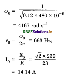
(b) Power absorbed is also maximum at the resonating frequency
V0 = 663 Hz
When I0 = 14.14 A
So [Pav]max = \(\frac{1}{2}\)I02R = \(\frac{1}{2}\) x (14.14)2 x 23 = 2300 W
(c) At ω = ω0 ±\(\frac{\mathrm{R}}{2 \mathrm{~L}}\) [Approximation good if \(\frac{\mathrm{R}}{2 \mathrm{~L}}\) << ω0]
∆ω = \(\frac{\mathrm{R}}{2 \mathrm{~L}}=\frac{23}{0.24}\) = 95.8 rad s-1
i.e. ∆v = \(\frac{\Delta \omega}{2 \pi}=\frac{95.8}{2 \times 3.142}\) = 15.2 Hz
∴ Power absorbed is half the peak power at v = 663 ± 15 = 648 Hz and 678 Hz
At these frequencies, current amplitude is \(\left(\frac{1}{\sqrt{2}}\right)\) times I0 i.e. current amplitude (at half the peak power points) is
\(\frac{\mathrm{I}_0}{\sqrt{2}}=\frac{14.14}{\sqrt{2}}\) = 10 A
(d) Q-factor = \(\frac{\omega_0 \mathrm{~L}}{\mathrm{R}}=\frac{4167 \times 0.12}{23}\) = 21.7.
Question 7.21.
Obtain the resonant frequency and Q-factor of a series LCR circuit with L = 3.0 H, C = 27 µF and R = 7. 4 Ω. It is desired to improve the sharpness of the resonance of the circuit by reducing its full width at half maximum by a factor of 2. Suggest a suitable way.
Answer:
ω0 = \(\frac{1}{\sqrt{\mathrm{LC}}}\),
So v = \(\frac{1}{2 \pi \sqrt{3 \times 27 \times 10^{-6}}}\) = 111.1 rad s-1
and Q = \(\frac{\omega_0 \mathrm{~L}}{\mathrm{R}}\) = 45.04
To double Q without changing ω0, reduce R to 3.7 Ω.
Question 7.22.
Answer the following questions:
(а) In any a.c. circuit, the applied instantaneous voltage is equal to the algebraic sum of the instantaneous voltage across the series elements of the circuit? Is the same true for rms voltage?
(b) A capacitor is used in the primary circuit of an induction coil.
(c) An applied voltage signal consists of a superposition of a d.c. voltage and an a.c. voltage of high frequency. The circuit consists of an inductor and a capacitor in series. Show that the d.c. signal will appear across C and the a.c. signal across L.
(d) A choke coil in series with a lamp is connected to a d.c. line. The lamp is seen to shine brightly. Insertion of an iron core in the choke causes no change in the lamp’s brightness. Predict the corresponding observations if the connection is to an a.c. line.
(e) Why is choke coil needed in the use of the fluorescent tubes with a.c. mains? Why can we not use an ordinary resistor instead of choke coil?
Answer:
(a) Yes. The same is not true for rms voltage, because voltages across different elements may not be in phase.
(b) When the circuit is broken the high induced voltage is used to charge the capacitor, thus avoiding sparks etc.
(c) For d.c. impedance of L is negligible and of C very high infinite so the d.c. signal appears across C. For high ω a.c., impedance of L high and that of C low. So the a.c. signal appears across L.
(d) For steady-state d.c. L has no effect, even if it is increased by an iron core. For a.c. the lamp will shine dimly because of additional impedance of the choke. It will dim further when the iron core is in¬serted which increases the choke’s impedance.
(e) A choke coil reduces voltage across the tube without wasting power. A resistor would waste power in the form of heat.
Question 7.23.
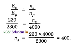
A power transmission line feeds input power at 2300 V to a stepdown transformer with its primary winding having 4000 turns. What should be the number of turns in the secondary windings in order to get output power at 230 V?
Answer:
Question 7.24.
At a hydroelectric power plant, the water pressure reading is 103 at a height of 300 m and the water flow available is 100 m3s-1. If the turbine generator efficiency is 60%, estimate the electric power available from the plant (g = 9.8 ms-2).
Answer:
Hydroelectric power = \(\frac{\text { Work }}{\text { Time }}=\frac{\mathrm{F} \times \mathrm{S}}{t}\) = PA v
hρg x A x v = hρgV
where V = A v is the flow (volume of water flowing per second across a cross-section). Given efficiency of generator = 60% = 0.6
Efficiency = \(\frac{\text { OutputPower }}{\text { Input }}\)
Output power = 0.6 x 300 x 103 x 9.8 x 100 MW
= 176.4 MW.
Question 7.25.
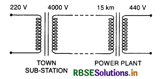
A small town with a demand of 800 k W of electric power at 220 V is situated 15 km away from an electric plant generating power at 440 V. The resistance of the two wire line carrying power is 0.5 Ω per km. The town gets power from the lines through at 4000-220 V step-down transformer at a substation in the town.
(a) Estimate the line power loss in the form of heat.
(b) How much power must the plant supply, assuming there is negligible power loss due to leakage?
(c) Characterize the step-up transformer at the plant.
Answer:
Line resistance = 30 x 0.5 = 15 Ω
r.m.s. current in the line = \(\frac{\text { Power }}{\text { Voltage }}\)
\(\frac{800 \times 1000}{4000}\) = 200 A
(a) Line power loss = I2 R
= 200 x 200 x 15 = 600 KW
(b) Power supply by the plant = Power required at sub-station + loss of power on transmission
= 800 + 600 = 1400 kW
(c) Voltage drop on the line
= \(\frac{\text { Power }}{\text { Current }}=\frac{1400 \times 10^3}{200}\)
or Voltage drop = 7000 V
The step-up transformer at the plant is 440 V - 7000 V.
Question 7.26.
Do the same exercise as above with the replacement of the earlier transformer by a 40,000 - 220 V step-down transformer? (Neglect, as before, leakage losses though this may not be a good assumption any longer because of the very high voltage transmission involved ). Hence explain why high-voltage transmission is preferred.
Answer:
Primary current required = \(\frac{800 \times 1000 \mathrm{~W}}{40,000 \mathrm{~V}}\)
= 20 A
(a) Line power loss = I2 R
or line power loss = 20 x 20 x 15 = 6kW
The line power loss becomes 1/10 of that in previous case because line current becomes 1/10th times
(b) Power supply by the plant = 800 +6 = 806 kW
(c) Voltage drop on the line = IR
= 20 x 15 = 300 V
The step-up transformer is 40,000 + 300 = 40300 V It is clear from Q. 7.25 and 7.26 that percentage power loss is greatly reduced by high voltage transmission, in Q. 7.25, this power loss is:
\(\frac{600}{1400}\) x 100 = 43%
In Q. 7.26, this power loss is only
\(\frac{6}{806}\) x 100 = 0.74%.

- RBSE Class 12 Physics Notes Chapter 2 स्थिर वैद्युत विभव तथा धारिता
- RBSE Class 12 Physics Notes Chapter 3 विद्युत धारा
- RBSE Class 12 Physics Notes Chapter 4 गतिमान आवेश और चुंबकत्व
- RBSE Class 12 Physics Notes Chapter 5 चुंबकत्व एवं द्रव्य
- RBSE Class 12 Physics Notes Chapter 6 वैद्युत चुंबकीय प्रेरण
- RBSE Class 12 Physics Notes Chapter 7 प्रत्यावर्ती धारा
- RBSE Class 12 Physics Notes Chapter 8 वैद्युतचुंबकीय तरंगें
- RBSE Class 12 Physics Notes Chapter 9 किरण प्रकाशिकी एवं प्रकाशिक यंत्र
- RBSE Class 12 Physics Notes Chapter 10 तरंग-प्रकाशिकी
- RBSE Class 12 Physics Notes Chapter 11 विकिरण तथा द्रव्य की द्वैत प्रकृति
- RBSE Class 12 Physics Notes Chapter 12 परमाणु