RBSE Class 12 Physics Important Questions Chapter 7 Alternating Current
Rajasthan Board RBSE Class 12 Physics Important Questions Chapter 7 Alternating Current Important Questions and Answers.
Rajasthan Board RBSE Solutions for Class 12 Physics in Hindi Medium & English Medium are part of RBSE Solutions for Class 12. Students can also read RBSE Class 12 Physics Important Questions for exam preparation. Students can also go through RBSE Class 12 Physics Notes to understand and remember the concepts easily. Browsing through wave optics important questions that include all questions presented in the textbook.
RBSE Class 12 Physics Chapter 7 Important Questions Alternating Current
Multiple Choice Questions
Question 1.
Direct current cannot flow through:
(A) inductor
(B) capacitor
(C) resistor
(D) semi conductor.
Answer:
(B) capacitor

Question 2.
The r.m.s. value of a.c. is 220V. Nearly the peak value of a.c. is:
(A) 220 V
(B) 311V
(C) 211V
(D) 50 V.
Answer:
(B) 311V
Question 3.
What is the frequency of household supply of a.c. in India?
(A) zero
(B) 60 Hz
(C) 50 Hz
(D) None of these.
Answer:
(C) 50 Hz
Question 4.
Dynamo works on the principle of:
(A) Electromagnetic induction
(B) Heating effect of current
(C) Chemical effect of current
(D) None of the above.
Answer:
(A) Electromagnetic induction
Question 5.
The minimum and maximum values of power factor in an a.c. circuit are respectively:
(A) 0 and 1
(B) 0.1 and 1
(C) 1 and 2
(D) 1 and 1.5.
Answer:
(A) 0 and 1
Question 6.
Average power of an a.c. circuit is:
(A) EvIv sin Φ
(B) EvIv cos Φ
(C) EvIv
(D) None of these.
Answer:
(B) EvIv cos Φ
Question 7.
In an a.c. circuit, maximum value of voltage is 423 volt. Its effective voltage is:
(A) 323 V
(B) 340 V
(C) 400 V
(D) 300 V.
Answer:
(D) 300 V.
Question 8.
A capacitor:
(A) Offers easy path to a.c., but blocks d.c.
(B) Offers easy path to d.c. but blocks a.c.
(C) Offers easy path to both a.c. and d.c.
(D) Blocks a.c.
Answer:
(A) Offers easy path to a.c., but blocks d.c.
Question 9.
In a step-up transformer, the number of turns in:
(A) primary coil is more than secondary coil
(B) secondary coil is more than primary coil
(C) Both the coils are the same
(D) None of these.
Answer:
(B) secondary coil is more than primary coil
Question 10.
Working principle of an a.c. generator makes use of:
(A) Fleming left hand rule
(B) Fleming right hand rule
(C) Maxwell’s cork screw rule
(D) Ampere’s thumb rule.
Answer:
(B) Fleming right hand rule
Question 11.
In an a.c. circuit, the a.c. meters measures:
(A) r.m.s. values
(B) Peak values
(C) Mean values
(D) Mean square values.
Answer:
(A) r.m.s. values
Question 12.
The core of the transformer is laminated so that:
(A) ratio of voltages in primary and secondary coils may be increased
(B) energy loss due to eddy currents may be minimised
(C) weight of the transformer may be reduced
(D) residual magnetism in the core may be reduced.
Answer:
(B) energy loss due to eddy currents may be minimised
Question 13.
When a.c. passes through a capacitor, the current:
(A) leads voltage by phase π
(B) remains in phase with voltage
(C) leads voltage by phase \(\frac{\pi}{2}\)
(D) lags voltage by phase \(\frac{\pi}{2}\).
Answer:
(C) leads voltage by phase \(\frac{\pi}{2}\)
Question 14.
Can a.c. be used for electrolysis? Why?
(A) No, no fixed polarity
(B) Yes, no fixed polarity
(C) Yes, fixed polarity
(D) None of these.
Answer:
(A) No, no fixed polarity
Question 15.
When a.c. passes through pure resistance, then:
(A) e.m.f. leads the current by \(\frac{\pi}{2}\)
(B) e.m.f. lags behind the current by \(\frac{\pi}{2}\)
(C) e.m.f. and current are in the same phase
(D) e.m.f. leads the current by \(\frac{\pi}{4}\).
Answer:
(C) e.m.f. and current are in the same phase
Question 16.
Phase difference between voltage and current in an a.c. circuit having resistor only is:
(A) \(\frac{\pi}{2}\)
(B) \(\frac{\pi}{2}\)
(C) π
(D) Zero.
Answer:
(D) Zero.
Question 17.
Transformer does not work on:
(A) a.c.
(B) d.c.
(C) Both a.c. and d.c.
(D) None of these.
Answer:
(B) d.c.
Question 18.
Transformer is based upon the principle of:
(A) self induction
(B) mutual induction
(C) eddy currents
(D) none of these.
Answer:
(B) mutual induction
Question 19.
For the current in LCR circuit to be maximum.
(A) XL = 0
(B) XC = 0
(C) XL = XC
(D) R = XL + XC.
Answer:
(C) XL = XC
Question 20.
Alternating current cannot be measured by d.c. ammeter because:
(A) a.c. cannot pass through a.c. ammeter
(B) a.c. changes direction
(C) Average value of current of complete cycle is zero
(D) d.c. ammeter will get damaged.
Answer:
(C) Average value of current of complete cycle is zero
Question 21.
The instantarfeous current from a.c. source is:
I = 5 sin 314t. What is peak value of current?
(A) \(\frac{5}{\sqrt{2}}\) A
(B) 5\(\sqrt{2}\)A
(C) 5A
(D) None of these.
Answer:
(C) 5A
Question 22.
Why there is no power loss in an ideal inductor?
(A) P.F. of an ideal inductor is unity
(B) P.F. of an ideal inductor is zero
(C) Material is less free
(D) None of these.
Answer:
(B) P.F. of an ideal inductor is zero
Question 23.
Energy dissipated in LCR circuit is:
(A) L only
(B) C only
(C) R only
(D) all of above.
Answer:
(C) R only
Question 24.
Average power dissipated in pure capacitor in a.c. circuit is:
(A) \(\frac{1}{2}\)CV2
(B) CV2
(C) 2CV2
(D) Zero.
Answer:
(B) CV2
Question 25.
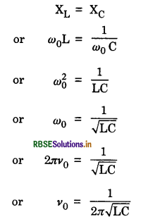
What is the condition of resonance?
(A) When XL = XC
(B) When XL < XC
(C) When XL > XC
(D) None of these.
Answer:
(A) When XL = XC
Fill in the blanks
Question 1.
Mean value of a.c. is ................................ time the maxium value of the current.
Answer:
0.637.
Question 2.
A.C. is measured by ................................ ammeter.
Answer:
hot wire.
Question 3.
Effective value of a.c. is ................................ times the peak value the current.
Answer:
0.707.
Question 4.
An inductor offers ................................ resistance to the flow of direct current through it.
Answer:
no.
Question 5.
The inductive reactance has the unit of ................................ .
Answer:
resistance.
Question 6.
A capacitor is a ................................ for d.c.
Answer:
block.
Question 7.
Mean value of a.c. over a complete cycle is ................................ .
Answer:
zero.
Question 8.
Resistance of a capacitor is practically ................................ .
Answer:
infinite.
Question 9.
At resonance, amplitude of current is ................................ and impedance is ................................ .
Answer:
Maximum, minimum.
Question 10.
A transfer cannot be used on ................................ mains.
Answer:
d.c.
Very Short Answer Type Questions
Question 1.
What are mean value and RMS value of A.C.?
Answer:
Mean current is that steady current which sends the same charge through a circuit in the same time as the a.c. does in half of its time period.
R.M.S. value of current is that steady current which produces the same amount of heat through a resistance in the same time as the alternating current does in the same resistance in the same time.
Question 2.
Write average value of a.c. for one cycle.
Answer:
Average value is zero.
Question 3.
Instantaneous voltage from an a.c. source is given by E = 300 sin 314 t. What is the r.m.s. voltage of the source?
Answer:
Given E = 300 sin 314t
Comparing it with general equation,
E = E0 sin ωt
∴ R.M.S. voltage,
Ev = \(\frac{\mathrm{E}_0}{\sqrt{2}}=\frac{300}{\sqrt{2}}\) = 300 x 0.707
= 212.1 V
Question 4.
Which effect of electric current is independent of the direction of its flow?
Answer:
Heat effect of current.
Question 5.
A household supply of a.c. in India has a peak value of 311 V and a frequency of 50 Hz. Write the equation to represent the same.
Answer:
The equation is E = E0 sin ωt
or E = 311 sin 100 πt [∵ ω = 2πv]
Question 6.
Peak value of an a.c. source is E0. What is its r.m.s. value?
Answer:
Erms = \(\frac{\mathbf{E}_0}{\sqrt{2}}\)
Question 7.
Write expression for current in an A.C. circuit with inductor only.
Answer:
The required expression is,
I = I0 cos {ωt - π/2).
Question 8.
Write expression for the energy stored in an inductor (i) at peak values (ii) after a complete cycle, with an A.C. source.
Answer:
The required expressions are,
(i) at peak values, W = \(\frac{1}{2}\) LI02
(ii) at end of cycle, W = 0.
Question 9.
Write expression for the energy stored in a capacitor (i) at peak values (ii) after a complete cycle with an A.C. source.
Answer:
The required expressions are:
(i) at peak values, W = \(\frac{1}{2}\) CV02
(ii) at end of cycle, W = 0.
Question 10.
What is common in L/R and CR?
Answer:
Both of them have the units of time and are called time constants.
Question 11.
Why does an LC circuit I produce oscillations?
Answer:
Due to change of electrostatic energy into magnetic energy and vice versa, oscillations are produced.
Question 12.
Frequency of a.c. source is doubled. How do R, XL and XC get affected?
Answer:
The value of resistance R in the circuit remains the same. The value of inductive resistance XL is doubled (since XL = 2πvL) and the value of capacitor resistance [since XC = 1/(2πvC)] is halved.
Question 13.
In an a.c. circuit, why is there no power consumption for an ideal inductor?
Answer:
The power in an a.c. circuit is wattless as phase difference of 90° exists between current and voltage.
Power = Iv. Ev cos Φ
Since current and voltage have a difference of 90°,
∴ Power = Iv. Ev cos 90° = 0.
Question 14.
A lamp is connected in series with a capacitor. What will happen if d.c. or a.c. is connected to current?
Answer:
For d.c. (v = 0), its resistance is infinite because XC = 1/(2πvC) and the lamp will not shine at all. If, however, a.c. is connected, the lamp will shine as capacitor conducts alternating current. Its resistance for a.c. is finite.
Question 15.
Which is more dangerous, a.c. or d.c.?
Answer:
The a.c. is more dangerous than d.c. The 200 V a.c. (r.m.s value) is having peak value 220 \(\sqrt{2}\) = 311 V. Hence, 220 V a.c. is as much dangerous as 3.11 V d.c. is. Also a.c. is attractive whereas d.c. is repulsive.
Question 16.
A resistance of 6 ohm is connected in series with inductor and capacitor having reactances 36 and 44 ohm respectively. What is the combined impedance?
Answer:
Impedance = \(\sqrt{\mathrm{R}^2+\left(\mathrm{X}_{\mathrm{L}}-\mathrm{X}_{\mathrm{C}}\right)^2}\)
or Z = \(\sqrt{(6)^2+(36-44)^2}\)
= \(\sqrt{36+64}\) = 10 ohm.
Question 17.
How does capacitor behave to d.c.?
Answer:
A capacitor offers infinite resistance to d.c.
[XC = 1/(2πv C) = 1/(2π x 0 x C) = ∞] and so d.c. cannot pass through it.
Question 18.
What value of a.c. is given by an a.c. ammeter?
Answer:
An a.c. ammeter gives RMS value of the current. If the maximum current is Imax, then the RMS value measured by an ammeter will be
Iv = \(\frac{I_{\max }}{\sqrt{2}}=\frac{I_0}{\sqrt{2}}\)
Question 19.
Give the expression for the energy stored in a capacitor and an inductor.
Answer:
Energy in a capacitor is given by \(\frac{1}{2}\) CV2 and in an inductor energy is given by \(\frac{1}{2}\) LI2.
Question 20.
What is sharpness of resonance?
Answer:
Sharpness of resonance is defined as the ratio of resonance frequency to the difference in the frequencies on both sides of the current in the circuit falling to \(\frac{1}{\sqrt{2}}\) of its value at resonance.
Question 21.
Write expression for current in a series LCR circuit with a.c. source.
Answer:
The required expression is,
I = I0 cos (ωt - θ).
Question 22.
Write expression for current in A.C. circuit with resistor only.
Answer:
The required expression is, I = I0 cos ωt
where I0 = \(\frac{E_0}{R}\)
Question 23.
Write expression for angular resonant frequency in series LCR circuit with A.C. source.
Answer:
The required expression is ω = \(\frac{1}{\sqrt{\mathrm{LC}}}\)
Question 24.
Give phase relation between current and voltage in a series LCR circuit with A.C. source.
Answer:
The current lags behind the voltage by angle θ = tan-1\(\frac{Z}{R}\).
Question 25.
Write expression for average power consumed by a resistor from an a.c. source.
Answer:
The required expression is,
P = Er.m.s Ir.m.s.
Question 26.
Give phase relation between current and voltage in an A.C. circuit with capacitor only.
Answer:
The current leads ahead in phase from the voltage by π/2.
Question 27.
Give phase relation between current and voltage in an A.C. circuit with inductor only.
Answer:
The current lags behind in phase from the voltage by π/2.
Question 28.
What is meant by the statement that the current through an inductor lags e.m.f. across it by π/2.
Answer:
It means that if e.m.f. is maximum at any instant in the circuit, then current will become maximum after a time T/4 (T is time period of a.c.)
Question 29.
What is the power factor of an LCR series circuit at resonance?
Answer:
Power factor,
cos Φ = \(\frac{\mathrm{R}}{\sqrt{\mathrm{R}^2+\left(\omega \mathrm{L}-\frac{1}{\omega C}\right)^2}}\)
In series resonance condition,
ωL = \(\frac{1}{\omega \mathrm{C}}\)
cos Φ = \(\frac{\mathrm{R}}{\mathrm{R}}\) = 1
Question 30.
The instantaneous current from an a.c. source is i = 0.5 sin 314 t. What is the
(i) r.m.s. value,
(ii) frequency of the current?
Answer:
Given i = 0.5 sin 314 t
∴ i0 = 0.5 A and ω = 314t rad s-1
(i) irms = \(\frac{i_0}{\sqrt{2}}\) = 0.707 x 0.5 = 0.35 A
(ii) ω = 2πv
∴ v = \(\frac{\omega}{2 \pi}=\frac{314}{2 \times 3.14}\) = 50 Hz
Question 31.
What is iron loss in a transformer?
Answer:
Iron loss is the loss of energy in the form of heat in the iron core of the transformer.
Question 32.
In an LR circuit, reactance and resistance are equal. Calculate phase by which voltage differ current?
Answer:
tan Φ = \(\frac{X_L}{R}=\frac{X_L}{X_L}\) = 1
or Φ = 45°.
Question 33.
When does a series LCR circuit have minimum impedance?
Answer:
At resonance.
Question 34.
What is the real place of energy in case of charging capacitor?
Answer:
The electric field within the capacitor plates.
Question 35.
What is the nature of charge in an LC-circuit?
Answer:
Oscillatory in nature.
Question 36.
The power factor of an a.c. circuit is 0.5. What will be the phase difference between voltage and current?
Answer:
Given cos Φ = 0.5, so Φ = π/2.
Question 37.
What do you mean by impedance of a circuit?
Answer:
Impedance is the effective resistance offered to the flow of a.c.
Question 38.
What do you mean by the term admittance? What is its unit?
Answer:
The admittance of an a.c. circuit, is the reciprocal of its impedance. Its unit is Ω-1.
Question 39.
What do you mean by wattless current?
Answer:
The current is said to be wattless if there is no power consumption in the circuit.
Question 40.
What can we say about the current in LCR series resonance?
Answer:
The amplitude of current is maximum.
Question 41.
Are losses in transformer avoidable?
Answer:
No.
Question 42.
Peak value of an a.c. source E0. What is its r.ms. value?
Answer:
Erms = \(\frac{\mathrm{E}_0}{\sqrt{2}}\)
Question 43.
The instantaneous current from an a.c. source is i = 0.5 sin 314 t. What is the
(i) r.ms. value,
(ii) frequency of the current?
Answer:
Given i = 0.5 sin 314 t
∴ i0 = 0.5 A and ω = 314 t rad s-1
(i) irms = \(\frac{i_0}{\sqrt{2}}\) = 0.707 x 0.5 ≃ 0.35 A
(ii) ω = 2πv
∴ v = \(\frac{\omega}{2 \pi}=\frac{314}{2 \times 3.14}\) = 50 Hz
Question 44.
What is the phase difference between the voltage across an inductor and a capacitor in an a.c. circuit?
Answer:
180°
Question 45.
Give expression for the average value of the a.c. voltage V = V0 sin ωt over the time interval t = 0 and t = \(\frac{\pi}{\omega}\).
Answer:
t = \(\frac{\pi}{\omega}=\frac{\pi \mathrm{T}}{2 \pi}=\frac{\mathrm{T}}{2}\) i.e. half cycle
∴ Vav = \(\frac{2}{\pi}\)V0 = 0.707 V0
Question 46.
An electrical element X, when connected to an alternating voltage source, has the current through it leading the voltage by π/2 rad. Identify X and write an expression for its reactance.
Answer:
Since the current through it leads the voltage by π/2 so the element is a capacitor. And reactance,
XC = \(\frac{1}{\omega \mathrm{C}}=\frac{1}{2 \pi \nu \mathrm{C}}\)
Question 47.
The power factor of an a.c. circuit is 0.5. What will be the phase difference between voltage and current?
Answer:
Given cos Φ = 0.5, so Φ = π/2.
Question 48.
What is the significance of Q factor in a series LCR resonant circuit?
Answer:
The Q factor in a series LCR resonant circuit signifies the selective sharpness of tuned LCR circuit.
Question 49.
What is the power dissipated in an ax. circuit in which voltage and current are given by V = 3000 sin (ωt - \(\frac{\pi}{2}\)) and I = 10 sin ωt
AnsWER:
Power dissipated in a.c. circuit is given by
P = VI cos Φ
Here Φ = \(\frac{\pi}{2}\)
So P = VI cos 90° = 0
Question 50.
In India domestic power supply is at 220 V, 50 Hz. While in USA it is 110 V, 50 Hz. Given one advantage and one disadvantage of 220 V supply over 110 V supply.
Answer:
At 220V; 50 Hz current is less, hence, power loss is also less.
Question 51.
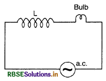
A bulb and a capacitor are connected in series to an a.c. source of variable frequency. How will the brightness of the bulb change on increasing the frequency of the source? Explain reasons.
Answer:
Since XC = \(\frac{1}{2 \pi \nu \mathrm{C}}\) or XC ∝ \(\frac{1}{v}\)
So as v increases, XC and hence IXC (voltage across capacitor) decreases, therefore the voltage across the bulb increases and hence the brightness of the bulb increases.
Question 52.
An alternating current from a source is represented by I = 10 sin 314t.
Write the corresponding value of
(i) Its effective value and (ii) frequency of the source.
Answer:
Since I = 10 sin 314 t
So I0 = 10 units and ω = 314 rad s-1
So (i) effective value, Ieff = \(\frac{\mathrm{I}_0}{\sqrt{2}}\)
= 0.707 x 10 = 7.07 units
(ii) Frequency of source,
v = \(\frac{\omega}{2 \pi}=\frac{314}{2 \times 3.14}\) = 50 Hz
Question 53.
Give the phase difference between the applied a.c. voltage and the current in an LCR circuit at resonance.
Answer:
Zero.
Question 54.
Define the term “wattless current.
Answer:
The wattless current is that in which there is no consumption of power is involved for its maintenance in the circuit. An ac current containing only capacitor or inductor, the current is called wattless.
Question 55.
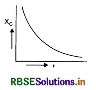
Draw the graph to show that the variation of XC with the frequency of the a.c. source used.
Answer:
The graph between XC and v is as shown in figure VSAQ 55.
Question 56.
Why can’t transformer be used to step up d.c. volatage?
Answer:
Because there is no variation of field by d.c. voltage and hence induced emf cannot produced in the secondary of the transformer.
Question 57.
Which is the best method of reducing current in an a.c. circuit and why?
Answer:
The best method is to use inductive reactance in the circuit. Because an inductor offers reactance without any power loss.
Question 58.
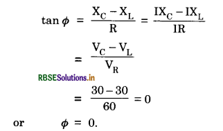
In a series LCR circuit the voltage across an inductor, a capacitor and a resistor are 30V, 30V and 60 V respectively. What is the phase difference between the applied voltage and current in the circuit?
Answer:
Here VL = 30 V, VC = 30 V and VR = 60 V
In LCR circuit, the phase difference between applied voltage and current is
Question 59.
What is the power dissipation in an a.c. circuit in which voltage and current are given by V = 300 sin (ωt + -\(\frac{\pi}{2}\)) and i = 5 sin ωt?
Answer:
Since phase difference between voltage and current is Φ = 90°
∴ Power factor = cos Φ = cos 90° = 0
Hence power dissipation is zero.
Short Answer Type Questions
Question 1.
Define root mean square or virtual or effective value of a.c.
Answer:
It is that steady current which when passed through a given resistor for a certain time, produces the same amount of heat as a.c. produces when passed through the same resistor for the same time.
Question 2.
Derive expression for Average or Mean Value of Alternating Current over one complete cycle.
Answer:
Average or Mean Value of Alternating Current over one complete cycle.
The instantaneous value of an alternating current is given by:
I = I0 sin ωt
Its average value over one complete cycle will be given as:
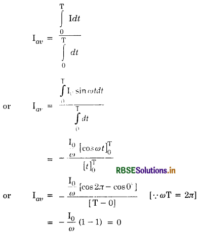
Thus the average value of alternating current over one complete cycle (or over any number of complete cycles) is zero. Similarly the average value of alternating e.m.f. over complete cycle is also zero.
As D.C. instruments measure average values of the quantities, they will record zero reading, and will fail to measure A.C. quantities.
Question 3.
What do you mean by lag and lead in alternating current?
Answer:
In a D.C. supply the e.m.f. and current are always in the same phase and there is nothing like ‘lag’ or ‘lead’ but in an A.C. supply, although the e.m.f. and current have the same frequency, yet they may be out of phase with each other, i.e. the peak value of e.m.f. and peak value of current may not occur at the same time. This brings in the idea of ‘lag’ and ‘lead’ in an A.C. circuit. If the peak value of e.m.f. occurs before the peak value of current, the e.m.f. is used to ‘lead’ the current or current is said to ‘lag’ behind the e.m.f. by a certain angle of fraction of the time period. The exact value of ‘lag’or ‘lead’ depends on the nature of circuit.
Question 4.
Can we define the r.m.s. value of a.c. in terms of the chemical effect of current?
Answer:
No, because, chemical effects are reversed when the direction of current is reversed.
Question 5.
Why an inductor is an easy path for d.c. and resistive path for a.c.?
Answer:
The inductive reactance (resistance offered by inductor) of an inductor is given by
XL = ωL = 2πv L
When v is the frequency of a.c. source.
For d.c. v = 0
∴ XL = 2π0.L = 0
i.e. the inductor offers no resistance to d.c.
For a.c.
v is finite
∴ XL ∝ v
So larger the value of v, more will be the effective resistance offered by the inductor.
Hence an inductor is an easy path for d.c. but a resistive path for a.c.
Question 6.
Show that a capacitor is an easy path for a.c. but a block for d.c. (i.e. offers infinite resistance for d.c.).
Answer:
The capacitive reactance XC (resistance offered by a capacitor) is given by
XC = \(\frac{1}{\omega \mathrm{C}}=\frac{1}{2 \pi v \mathrm{C}}\)
where C is the capacitance of the capacitor and v is the frequency of a.c. source.
For d.c.
v = 0
∴ XC = \(\frac{1}{0}\) = ∞
i.e. capacitor offers infinite resistance to d.c, in other words it blocks d.c.
For a.c., v is finite
so XC ∝ \(\frac{1}{v}\)
So larger the value of v, smaller will be the value of XC. Hence capacitor is an easy path for a.c.
So a capcitor is an easy path for a.c. but a block for d.c.
Question 7.
An alternating voltage of frequency f is applied across LCR circuit. Let fr be the resonance frequency for the circuit. Will the current in the circuit lag, lead or remain in phase with the applied voltage when (i) f > fr, (ii) f < fr? Explain your answer in each case.
Answer:
In an LCR circuit, the phase angle Φ is given by
tan Φ = \(\frac{X_L-X_C}{R}\)
= \(\frac{2 \pi f \mathrm{~L}-\frac{1}{2 \pi f \mathrm{C}}}{\mathrm{R}}\)
(i) When f > fr, then XL > XC and the circuit is inductive dominant circuit and tan Φ is +ve. So the current will lag behind the applied voltage by a phase Φ.
(ii) When f < fr, then XL < XC and the circuit is capacitive dominant circuit, and tan Φ is - ve, so the current will lead the applied voltage by a phase Φ.
The current will remain in phase if f = fr then XL = XC and the circuit is purely resistive and hence current and voltage are in phase.
Question 8.
State the condition under which the phenomenon of resonance occurs in a series LCR circuit. Plot a graph showing the variation of current with frequency of an a.c. source in series LCR circuit.
Answer:
The condition for series resonance is

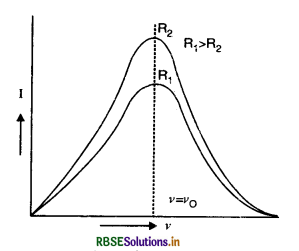
The graph between I and v is as shown in Fig.
Question 9.
State the underlying principle of an a.c. generator. Write the relationship between the peak values and r.m.s value of alternating voltage.
Answer:
Principle of a.c. generator. It is based on the principle of electromagnetic induction i.e. whenever magnetic flux linked with a coil changes, an induced e.m.f. is produced.
The relation between peak value and r.m.s. value of alternating voltage is
Ev = \(\frac{\mathrm{E}_0}{\sqrt{2}}\) = 0.707 E0
Question 10.
State the underlying principle of a transformer. Write two causes of power loss in it.
Answer:
Principle of a transformer. It is based on the principle of mutual induction i.e. whenever magnetic flux linked with a coil is changed, an induced e.m.f. is produced in the neighbouring coil.
Transformer. A transformer is a device for converting a large alternating current at low voltage into a small alternating current at high voltage and vice-versa.
If the voltage is stepped up and the current is decreased, the transformer is called step up transformer and if the voltage is lowered and the current is increased, the transformer is called step down transformer.
Principle. It is based upon the principle of mutual inductance i.e. whenever magnetic flux linked with a coil is changed, an induced e.m.f. is produced in the neighbouring coil.
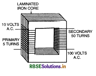
Construction. A transformer consists of two coils of insulated wire containing different number of turns wound separately on a continuous soft iron core as shown in Fig. LAQ 26. The coil to which the electric energy is fed is called the primary, whereas the coil from which the energy is drawn is called the secondary. The two coils of wire are close to each other but are not electrically connected. The entire magnetic flux coming out of one will practically remain in the iron core, and hence pass through the other coil. The soft iron core provides a good path for the magnetic lines of force and therefore, helps in making almost all of them pass through the secondary coil.

Action. Alternating current is fed to the primary. The alternating current in the primary produces an alternating magnetic flux in the core which passes through the secondary coil. Since magnetic flux remains practically confined within the core, the magnetic flux linked with the secondary is almost the same as that passing through the primary. The changing magnetic flux produces an induced e.m.f. in the secondary and also gives rise to self-induced (back) e.m.f. in the primary.
Consider the terminals of secondary coil to be open. Let Np and Ns be the number of turns in the primary and secondary coils respectively. Let Φ be the magnetic flux linked with the primary and the secondary at any instant. The induced e.m.f. in primary and secondary coils are given by:
Ep = -Np \(\frac{d \phi}{d t}\)
and Es = -Ns \(\frac{d \phi}{d t} \)
Thus \(\frac{\mathrm{E}_s}{\mathbf{E}_p}=\frac{\mathrm{N}_s}{\mathrm{~N}_p} \) ...........................(i)
The ratio of the number of turns in the secondary to that in the primary is called transformation ratio.
If a step up transformer, Ns > Np, i.e. the transformation ratio is greater than 1 so that Es > Ep.
In step down transformer, Ns < Np i.e., transformation ratio is less than 1. so that Es < Ep.
Output current. Further, according to the law of conservation of energy whether device is possible which can give any net gain of energy. Therefore, assuming no energy losses in the transformer, the energy drawn from the secondary is equal to that fed into the primary. Or, in other words,
Power output = Power input
If Ip and Is are the values of the currents in the primary and the secondary coils respectively, we have
Is Es = Ip Ep
or \(\frac{\mathrm{E}_s}{\mathrm{E}_p}=\frac{\mathrm{I}_p}{\mathrm{I}_s} \)
Thus as the voltage in the secondary increases, the current proportionately falls and vice versa i.e., whatever we gain in voltage, we stand to lose that much in current.
The efficiency of transformer is defined as
η = \(\frac{\text { Output power }}{\text { Input power }} \)
In an actual transformer, due to eddy currents in the core and also magnetic hysteresis of the core, part of the energy is actually lost.
Losses. Transformer is one of the most efficient machines known and its efficiency is high as 90-99%. It suffers from the following main losses
- Copper loss. Energy lost as heat produced in copper wire used in the winding when current is passed through them (given by I2R). This loss is minimized by using thick wire as their resistance is low.
- Iron loss. Energy lost due to eddy currents formed in the core. This can be eliminated by using laminated iron core.
- Hysteresis loss. It is the energy lost as work done in carrying the iron core through cycles of magnetization and demagnetization. This can be minimised by selecting iron with special magnetic properties to be used as core.
- Magnetic flux leakage. Due to imperfect insulation, some of the magnetic flux leaks and causes an energy loss.
- Humming loss. Due to passage of a.c. the core starts vibrating and produces humming sound. This sound production is called humming loss.
Uses
- Transformer is used in T.V., tape recorders, computers, air conditioners etc.
- In induction furnace.
- Step down transformer is used for welding purpose.
- Transformer is used for transmission of a.c. over long distances.
Question 11.
What is the difference between steady current and d.c.?
Answer:
In steady current, the magnitude of the current remains constant
In d.c., the current always flows in one direction and its direction is not reversed with time like a.c.
Question 12.
The divisions marked on the scale of an a.c. ammeter is not equally spaced. Why?
Answer:
Because a.c. ammeter is based on the principle of heating effect of current, and heat produced is proportional to the square of current (H ∝ I2) (and not proportional to current) so the divisions marked on the scale are not equally space.
Question 13.
The d.c. and a.c. both can be measured by hot wire instruments. Why?
Answer:
Hot wire meters are based on the heating effect of current. Since heat produced by both a.c. and d.c. is proportional to the square of current (H ∝ I2). Hence both d.c. and a.c. can be measured by hot wire instruments
[Note. The reversal of current in a.c. is immaterial as far as production of heat is concerned.]
Question 14.
At very high frequency of a.c. a capacitor behaves like conductor. Why?
Answer:
The capacitive reactance of a capacitor XC is given by:
XC = \(\frac{1}{2 \pi v \mathrm{C}}\)
or XC ∝ \(\frac{1}{v}\)
At very high frequency (i.e. at very high value of v) the value of XC is very small, hence a capacitor behaves like a conductor.
Question 15.
Show that the unit of CR and L/R are the same as those of time.
Answer:
Unit of CR = (Unit of C) (Unit of R)
= Farad x ohm
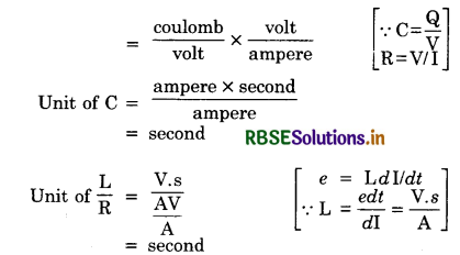
Question 16.
For circuit used for transporting electric power, a low power factor implies large power loss in transmission.
Answer:
To supply a given power, low power factor means a larger current is needed to transmit a certain power [since P = Iv Ev cos Φ]. This causes larger heat losses due to the factor I2R.
Question 17.
Power factor can often be improved by the use of capacitor of appropriate capacitance in the circuit.
Answer:
Power factor = \(\frac{\mathrm{R}}{\mathrm{Z}}\).
Impedence, Z = \(\sqrt{\mathrm{R}^2+\left(\mathrm{L} \omega-\frac{1}{\mathrm{C} \omega}\right)^2}\)
Many a.c. machines have inductance resistance. If a capacitor of appropriate capacitance is used, then the value of Z approaches the value of R. Thus the value of power factor can be improved.
Question 18.
An applied voltage sign consists of superposition of a d.c. voltage and an a.c. voltage of high frequency. The circuit consists of an inductor and a capacitor in series. Show that the d.c. signal will appear across capacitor C and a.c. signal across inductor L.
Answer:
For d.c. the impedance of inductor L (XL = 2πvL, for d.c. v = 0) is negligible and impedance of C is almost infinte [XC = 1/2 πv C]. As a result of it d.c. signal appears across C.
For high frequency a.c., impedance of C is low and that of L is very high. As a result of it a.c. signal appears across L.
Question 19.
A choke coil in series with a lamp is connected to d.c. source. The lamp is seen to shine brightly. Inserting an iron core in choke causes no change in the lamp’s brightness. What will happen if connection is made to an a.c. source?
Answer:
In the case of d.c., steady state is obtained and then inductance L has no effect since at v = 0, XL = 0. When an iron core is introduced, L increases but it is still ineffective. For a.c., the lamp will shine dimly because of additional impedance of choke. When iron core is introduced, its impedance increases further and it will become dim further.
Question 20.
What is the significance of -ve value of instantaneous current?
Answer:
The instantaneous value of a.c. is given by
I = I0 sin ωt.
The direction of current changes after every half cycle. The -ve value of instantaneous current indicates that if the direction of current is +ve in 1st half cycle, it is taken -ve during second half cycle.
Question 21.
Distinguish between resistance and resistor; inductance and inductor; capacitance and capacitor.
Answer:
Resistance is the property of a conductor due to which it opposes the growth of the current (or resists the flow of electrons) through it. The appliance which offers the resistance to the flow of current is called resistor.
Inductance is the phenomenon according to which an opposing induced e.m.f. is produced in a coil as a result of change in the current or magnetic flux linked with the coil. The appliance in which this effect is produced is called inductor.
Electrical capacitance of a conductor is related to its ability to store the electric charge.
Capacitor is a device for storing large quantity of electric charge.
In brief, resistance, inductance and capacitance are the properties of devices resistor, inductor and capacitor.
Question 22.
Distinguish between resistance, inductive reactance, capacitive reactance and impedance.
Answer:
Resistance is the property due to which conductor resists the flow of electrons through it. It is measured in ohm.
Reactance is the opposition offered by an inductor or a capacitor to the flow of a.c. through it. If it is due to an inductor, it is called inductive reactance and if it is due to capacitor, it is called capacitive reactance. Both are measured in ohm.
Inductive reactance of an inductor is the measure of its effective opposition to the flow of alternating current through it.
XL = 2πv L
For d.c. v = 0, hence inductive reactance does not offer any resistance to d.c. Greater the frequency, more the inductive reactance.
Capacitive reactance of a capacitor is the measure of opposition offered by the flow of current through it.
XC = \(\frac{1}{2 \pi v \mathrm{C}}\)
For d.c. v = 0; XC = ∞. Thus capacitor blocks d.c. Higher the frequency, lesser the reactance.
Impedance is the total opposition offered by L, C and R to the flow of a.c.
Impedance
Z = \(\sqrt{(\text { Resistance })^2+(\text { Reactance })^2}\)
or Z = \(\sqrt{\mathrm{R}^2+\left(\mathrm{X}_{\mathrm{L}}-\mathrm{X}_{\mathrm{C}}\right)^2}\)
Impedance plays the same role in a.c. as resistance plays in d.c. circuit. Both are measured in ohm.
Question 23.
State the factors on which induced e.m.f. in a coil rotating in a uniform magnetic field depends.
Answer:
Since magnitude of induced e.m.f. is given by e = nBAω
So induced e.m.f. depends upon
- Number of turns of the coil (n)
- Face area of the coil (A)
- Magnetic field strength (B)
- The angular velocity of the coil (ω)
Question 24.
Sketch a graph to show how the reactance of (i) a capacitor (ii) an inductor varies as a function of frequency.
Or
Draw the graphs showing variation of inductive reactance and capacitive reactance with frequency of applied a.c. source.
Answer:
(i) Capacitive reactance
XC = \(\frac{1}{\omega \mathrm{C}}=\frac{1}{2 \pi v \mathrm{C}}\)
i.e., XC ∝ \(\frac{1}{v}\)
More the frequency, lesser the XC and vice versa. The graph between XC and v is as shown in Fig. SAQ 25 (a).
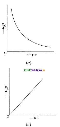
(ii) Inductive reactance,
XL = ωL
or XL = 2πvL
or XL ∝ v
i.e. inductive reactance is directly proportional to frequency.
The graph between XL and v is as shown in Fig. SAQ 25 (b)
Question 25.
Why can we not use the ordinary moving coil galvanometer for measuring a.c. current and voltage?
Answer:
In a.c. the magnitude and direction is changing continuously. During one half cycle it is in one direction and during next half cycle it is in reverse direction. So average current is zero, hence ordinary moving coil galvanometers cannot be used for measuring a.c. current and voltage. For measuring a.c. current and voltage, hot wire meters are used which are based.pn the heating effect of current. These meters measure virtual value of alternating current and voltage.
Question 26.
What is transformer?
Answer:
A transformer is an electrical device which convert a large ac at low voltage into a small a.c. at high voltage and vice versa with high efficiency.
Question 27.
Why is the core of a transformer laminated?
Answer:
The core of a transformer is laminated to reduce the energy loss due to eddy currents. The laminated core offers high resistance and hence magnitude of eddy current is reduced.
Question 28.
What are major factors which reduce the efficiency of a transformer?
Answer:
- Eddy current losses
- Copper losses
- hysteresis losses and
- magnetic flux leakage losses.
Question 29.
Can a transformer be used with d.c. voltage?
Answer:
No, because a transformer is based on the principle of mutual inductance, it cannot work with d.c. voltage which always remains constant.
Question 30.
What are the factors which help in increasing the efficiency of a transformer?
Answer:
- Laminated core decreases eddy current losses.
- Using a core material for which B-H loop has smaller area in order to reduce hysteresis loss.
Question 31.
Explain that the word generator is misnomer.
Answer:
The word generator is misnomer, as the generator generates nothing. It only converts mechanical energy into electrical energy.
Question 32.
A simple a.c. generator having a constant magnetic field is connected to a resistive load. Explain with reasons what will be the effects of doubling its speed of rotation on the following:
(a) frequency of rotation
(b) the generated em.f. and
(c) mechanical power required to rotate the generator.
Answer:
The maximum value of induced e.m.f. in a generator is given by
e = NBAω
(а) Frequency of rotation will be doubled.
(b) The e.m.f. will be doubled.
(c) Mechanical power will be doubled.
Question 33.
Can a capacitor of suitable capacitance replace a choke coil in an ac circuit?
Answer:
Both in a choke coil and in capacitor, the average power consumed is zero. So a capacitor of suitable capacitance can be replaced by a choke coil in an ac circuit.
Question 34.
Describe the use of transformer for long distance transmission of a.c.
Answer:
Long distance transmission of electric power. The most important use of a transformer is in the transmission of power from a generating station to the consumer. The following difficulties arise in such cases:
1. As the wires are many km long, they have an appreciable resistance so that a good portion of the electric energy is wasted as heat produced in the wires (heat produced being proportional to I2R).
2. For carrying heavy current and also to keep the resistance of the wires low, thick wires shall have to be used. But the cost of installing for very long thick wires will be very high.
3. Fall of potential (IR) is also high.
To avoid these difficulties, the voltage from the generator is increased by a step up transformer, so the current is lower. Heat produced will now be less, hence thin wires can be used and fall of potential also decreases. At the receiving end the voltage is reduced by using a step-down transformer as shown in the figure. High power transformers are immersed in oils to obtain good electric insulation and to provide a cooling medium.
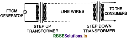
Bhakhra dam supplies electric power of 110 kV and then this voltage is reduced to usual 220 V with the help of step down transformer.
Question 35.
Radio frequency choke is air cored, whereas as audio frequency choke is iron cored. Explain.
Answer:
Radio frequency choke
The inductive reactance of choke is given by
XL = 2πv L
Radio frequency is very high frequency i.e v is large, so. XL is large. So in order to keep XL low, L should be low. This is possible only by using an air cored (µ = 1) inductance.
Audio frequency choke
In audio frequency choke, the frequency is low i.e. v is small. So to have reasonable value of XL, L should be high hence iron should be used for which the value of µ is high (because the value of L increases with µ).
Question 36.
Distinguish between the terms effective value and peak value of alternating current.
Answer:
Effective value (Eeff) of a.c. is the root of mean square value of current.
Peak value (I0) of a.c. the maximum value of the alternating current.
And Eeff = \(\frac{\mathrm{I}_0}{\sqrt{2}}\) = 0.707 I0
Question 37.
An electric lamp connected in series with a capacitor and an a.c. source is glowing with of certain brightness. How does the brightness of the lamp change on reducing the capacitance?
Answer:
Impedance of the circuit is
Z = \(\sqrt{\mathrm{R}^2+\mathrm{X}_{\mathrm{C}}^2}\)
And XC = \(\frac{1}{\omega \mathrm{C}}\)
So when the capacitance is reduced, XC increased and hence Z increases.
Since I = \(\frac{\mathrm{V}}{\mathrm{Z}}\). So I decreases and hence the brightness of the bulb is reduced.
Question 38.
What is the power dissipated by an ideal inductor in a.c. circuit? Explain.
Answer:
Since power dissipated is given by
P = Ev Iv cos Φ
For an ideal inductor cos Φ = 0.
So P = 0
i.e. power dissipated by an ideal inductor in a.c. circuit is zero.
Question 39.
Prove that an ideal capacitor in an a.c. circuit does not dissipate power.
Answer:
Power dissipated in a.c. circuit is
P = EvIv cos Φ
For an ideal capacitor,
cos Φ = 0
∴ P = 0
i.e. power dissipated in an ideal capacitor is zero.
Question 40.
An air cored coil L and a bulb B are connected in series to the a.c. mains as shown in the given figure SAQ 41:
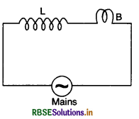
The bulb glows with some brightness. Now will the glow of the blub change if an iron rod is inserted in the coil? Give reason in support of your answer.
Answer:
When the iron rod is inserted in the coil, its inductance L will increase. This will increase inductive reactance XL = ωL. As the current Irms ∝ \(\frac{1}{\mathrm{X}_{\mathrm{L}}}\), so electric current in the circuit will decrease and the bulb glows dimmer or becomes less bright.
Question 41.
In the circuit shown below R represents an electric bulb. If the frequency (v = \(\frac{\omega}{2 \pi}\)) of the supply is doubled, how should the value of C and L should be changed so that the glow of bulb remains unchanged?
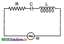
Answer:
If the current through the bulb is the same, the glow of the bulb will remain the same. The impedance of the LCR circuit is given by
Z = \(\sqrt{\mathrm{R}^2+\left(\omega \mathrm{L}-\frac{1}{\omega \mathrm{C}}\right)^2} \)
Since current has to be the same, therefore impedance must remain the same. For this to happen, the products ωL and ωC should remain same. Therefore if frequency is doubled both L and C must be halved.
Question 42.
An alternating voltage of frequency f is applied across LCR circuit. Let f be the resonance frequency for the circuit. Will the current in the circuit lag, lead or remain in phase with the applied voltage when (i) f > fr, (ii) f < fr? Explain your answer in each case.
Answer:
In an LCR circuit, the phase angle Φ is given by
tan Φ = \(\frac{X_L-X_C}{R}\)
= \(\frac{2 \pi f \mathrm{~L}-\frac{1}{2 \pi f \mathrm{C}}}{\mathrm{R}}\)
(i) When f > fr, then XL > XC and the circuit is inductive dominant circuit and tan Φ is +ve. So the current will lag behind the applied voltage by a phase Φ.
(ii) When f < fr, then XL < XC and the circuit is capacitive dominant circuit, and tan Φ is - ve, so the current will lead the applied voltage by a phase Φ.
The current will remain in phase if f = fr then XL = XC and the circuit is purely resistive and hence current and voltage are in phase.
Question 43.
State the condition under which the phenomenon of resonance occurs in a series LCR circuit. Plot a graph showing the variation of current with frequency of an a.c. source in series LCR circuit.
Answer:
The condition for series resonance is

The graph between I and v is as shown in Fig.
Question 44.
State the underlying principle of an a.c. generator. Write the relationship between the peak values and r.m.s value of alternating voltage.
Answer:
Principle of a.c. generator. It is based on the principle of electromagnetic induction i.e. whenever magnetic flux linked with a coil changes, an induced e.m.f. is produced.
The relation between peak value and r.m.s. value of alternating voltage is
Ev = \(\frac{\mathrm{E}_0}{\sqrt{2}}\) = 0.707 E0
Question 45.
State the underlying principle of a transformer. Write two causes of power loss in it.
Answer:
Principle of a transformer. It is based on the principle of mutual induction i.e. whenever magnetic flux linked with a coil is changed, an induced e.m.f. is produced in the neighbouring coil.
Transformer. A transformer is a device for converting a large alternating current at low voltage into a small alternating current at high voltage and vice-versa.
If the voltage is stepped up and the current is decreased, the transformer is called step up transformer and if the voltage is lowered and the current is increased, the transformer is called step down transformer.
Principle. It is based upon the principle of mutual inductance i.e. whenever magnetic flux linked with a coil is changed, an induced e.m.f. is produced in the neighbouring coil.
Construction. A transformer consists of two coils of insulated wire containing different number of turns wound separately on a continuous soft iron core as shown in Fig. LAQ 26. The coil to which the electric energy is fed is called the primary, whereas the coil from which the energy is drawn is called the secondary. The two coils of wire are close to each other but are not electrically connected. The entire magnetic flux coming out of one will practically remain in the iron core, and hence pass through the other coil. The soft iron core provides a good path for the magnetic lines of force and therefore, helps in making almost all of them pass through the secondary coil.

Action. Alternating current is fed to the primary. The alternating current in the primary produces an alternating magnetic flux in the core which passes through the secondary coil. Since magnetic flux remains practically confined within the core, the magnetic flux linked with the secondary is almost the same as that passing through the primary. The changing magnetic flux produces an induced e.m.f. in the secondary and also gives rise to self-induced (back) e.m.f. in the primary.
Consider the terminals of secondary coil to be open. Let Np and Ns be the number of turns in the primary and secondary coils respectively. Let Φ be the magnetic flux linked with the primary and the secondary at any instant. The induced e.m.f. in primary and secondary coils are given by:
Ep = -Np \(\frac{d \phi}{d t}\)
and Es = -Ns \(\frac{d \phi}{d t}\)
Thus \(\frac{\mathrm{E}_s}{\mathbf{E}_p}=\frac{\mathrm{N}_s}{\mathrm{~N}_p}\) ...........................(i)
The ratio of the number of turns in the secondary to that in the primary is called transformation ratio.
If a step up transformer, Ns > Np, i.e. the transformation ratio is greater than 1 so that Es > Ep.
In step down transformer, Ns < Np i.e., transformation ratio is less than 1. so that Es < Ep.
Output current. Further, according to the law of conservation of energy whether device is possible which can give any net gain of energy. Therefore, assuming no energy losses in the transformer, the energy drawn from the secondary is equal to that fed into the primary. Or, in other words,
Power output = Power input
If Ip and Is are the values of the currents in the primary and the secondary coils respectively, we have
Is Es = Ip Ep
or \(\frac{\mathrm{E}_s}{\mathrm{E}_p}=\frac{\mathrm{I}_p}{\mathrm{I}_s}\)
Thus as the voltage in the secondary increases, the current proportionately falls and vice versa i.e., whatever we gain in voltage, we stand to lose that much in current.
The efficiency of transformer is defined as
η = \(\frac{\text { Output power }}{\text { Input power }} \)
In an actual transformer, due to eddy currents in the core and also magnetic hysteresis of the core, part of the energy is actually lost.
Losses. Transformer is one of the most efficient machines known and its efficiency is high as 90-99%. It suffers from the following main losses
- Copper loss. Energy lost as heat produced in copper wire used in the winding when current is passed through them (given by I2R). This loss is minimized by using thick wire as their resistance is low.
- Iron loss. Energy lost due to eddy currents formed in the core. This can be eliminated by using laminated iron core.
- Hysteresis loss. It is the energy lost as work done in carrying the iron core through cycles of magnetization and demagnetization. This can be minimised by selecting iron with special magnetic properties to be used as core.
- Magnetic flux leakage. Due to imperfect insulation, some of the magnetic flux leaks and causes an energy loss.
- Humming loss. Due to passage of a.c. the core starts vibrating and produces humming sound. This sound production is called humming loss.
Uses
- Transformer is used in T.V., tape recorders, computers, air conditioners etc.
- In induction furnace.
- Step down transformer is used for welding purpose.
- Transformer is used for transmission of a.c. over long distances
Question 46.
An inductor L of reactance XL is connected in series with a bulb B to an a.c. source as shown in the figure. Briefly explain how does the brightness of the bulb changes when
(i) number of turns of the inductor is reduced and (ii) a capacitance of reactance XC = XL is included in series in the same circuit.
Answer:
(i) When the number of turns of the inductor is reduced, the value of XL will also decrease and thus more current will flow through the bulb and its brightness will increase.
(ii) When a capacitance of reactance XC = XL is included in series in the circuit, the circuit will be LCR circuit and it behaves as a resistive circuit and thus the current in the circuit and hence through the coil increase and the brightness of the bulb will increase.
Question 47.
Draw the graphs showing variation of inductive reactance and capacitive reactance with frequency of applied a.c. source.
Answer:
In a.c. the magnitude and direction is changing continuously. During one half cycle it is in one direction and during next half cycle it is in reverse direction. So average current is zero, hence ordinary moving coil galvanometers cannot be used for measuring a.c. current and voltage. For measuring a.c. current and voltage, hot wire meters are used which are based.pn the heating effect of current. These meters measure virtual value of alternating current and voltage.
Question 48.
An alternating voltage E = E0 sin ωt is applied to a circuit containing a resistor R connected in series with a black box. The current in the circuit is found to be I = I0 sin (ωt + \(\frac{\pi}{4}\)).
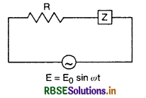
(i) State whether the element in the black box is a capacitor or inductor.
(ii) Draw the corresponding phasor diagram and find the impedance in terms of R.
Answer:
(i) Here we find that the current leads the voltage by a phase \(\frac{\pi}{4}\), so the element in the black box is a capacitor.
(ii) Phasor diagram is shown in fig. SAQ 49 (b)
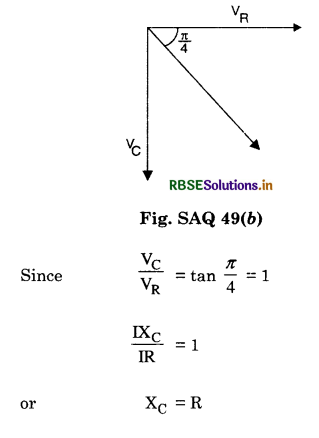
So Z = \(\sqrt{\mathrm{R}^2+\mathrm{X}_{\mathrm{C}}{ }^2}\)
= \(\sqrt{\mathrm{R}^2+\mathrm{R}^2}=\mathrm{R} \sqrt{2}\)
Question 49.
With the help of a diagram, explain the principle of the device which changes a low voltage into high voltage but does not violate the law of conservation of energy. Give any one reason why the device may not be 100% efficient.
Answer:
Transformer. A transformer is a device for converting a large alternating current at low voltage into a small alternating current at high voltage and vice-versa.
If the voltage is stepped up and the current is decreased, the transformer is called step up transformer and if the voltage is lowered and the current is increased, the transformer is called step down transformer.
Principle. It is based upon the principle of mutual inductance i.e. whenever magnetic flux linked with a coil is changed, an induced e.m.f. is produced in the neighbouring coil.
Construction. A transformer consists of two coils of insulated wire containing different number of turns wound separately on a continuous soft iron core as shown in Fig. LAQ 26. The coil to which the electric energy is fed is called the primary, whereas the coil from which the energy is drawn is called the secondary. The two coils of wire are close to each other but are not electrically connected. The entire magnetic flux coming out of one will practically remain in the iron core, and hence pass through the other coil. The soft iron core provides a good path for the magnetic lines of force and therefore, helps in making almost all of them pass through the secondary coil.
Action. Alternating current is fed to the primary. The alternating current in the primary produces an alternating magnetic flux in the core which passes through the secondary coil. Since magnetic flux remains practically confined within the core, the magnetic flux linked with the secondary is almost the same as that passing through the primary. The changing magnetic flux produces an induced e.m.f. in the secondary and also gives rise to self-induced (back) e.m.f. in the primary.
Consider the terminals of secondary coil to be open. Let Np and Ns be the number of turns in the primary and secondary coils respectively. Let Φ be the magnetic flux linked with the primary and the secondary at any instant. The induced e.m.f. in primary and secondary coils are given by:
Ep = -Np \(\frac{d \phi}{d t}\)
and Es = -Ns \(\frac{d \phi}{d t}\)
Thus \(\frac{\mathrm{E}_s}{\mathbf{E}_p}=\frac{\mathrm{N}_s}{\mathrm{~N}_p}\) ...........................(i)
The ratio of the number of turns in the secondary to that in the primary is called transformation ratio.
If a step up transformer, Ns > Np, i.e. the transformation ratio is greater than 1 so that Es > Ep.
In step down transformer, Ns < Np i.e., transformation ratio is less than 1. so that Es < Ep.
Output current. Further, according to the law of conservation of energy whether device is possible which can give any net gain of energy. Therefore, assuming no energy losses in the transformer, the energy drawn from the secondary is equal to that fed into the primary. Or, in other words,
Power output = Power input
If Ip and Is are the values of the currents in the primary and the secondary coils respectively, we have
Is Es = Ip Ep
or \(\frac{\mathrm{E}_s}{\mathrm{E}_p}=\frac{\mathrm{I}_p}{\mathrm{I}_s}\)
Thus as the voltage in the secondary increases, the current proportionately falls and vice versa i.e., whatever we gain in voltage, we stand to lose that much in current.
The efficiency of transformer is defined as
η = \(\frac{\text { Output power }}{\text { Input power }}\)
In an actual transformer, due to eddy currents in the core and also magnetic hysteresis of the core, part of the energy is actually lost.
Losses. Transformer is one of the most efficient machines known and its efficiency is high as 90-99%. It suffers from the following main losses
- Copper loss. Energy lost as heat produced in copper wire used in the winding when current is passed through them (given by I2R). This loss is minimized by using thick wire as their resistance is low.
- Iron loss. Energy lost due to eddy currents formed in the core. This can be eliminated by using laminated iron core.
- Hysteresis loss. It is the energy lost as work done in carrying the iron core through cycles of magnetization and demagnetization. This can be minimised by selecting iron with special magnetic properties to be used as core.
- Magnetic flux leakage. Due to imperfect insulation, some of the magnetic flux leaks and causes an energy loss.
- Humming loss. Due to passage of a.c. the core starts vibrating and produces humming sound. This sound production is called humming loss.
Uses
- Transformer is used in T.V., tape recorders, computers, air conditioners etc.
- In induction furnace.
- Step down transformer is used for welding purpose.
- Transformer is used for transmission of a.c. over long distances.
Long Answer Type Questions
Question 1.
What is alternating current? How alternating e.m.f. and current is represented mathematically. What do you mean by time period, frequency and amplitude of alternating current?
Answer:
Alternating current
The current in which both the magnitude and direction undergo a complete cycle of changes periodically is called alternating current. It increases from zero to a maximum value, then decreases to zero and reverses in direction. It once again becomes maximum in this direction and then reduced to zero. This complete set of variations in magnitude and direction of current or e.m.f. is called a cycle. During one cycle, the current flows in one direction, of course, changing in magnitude in the first half cycle and in the opposite direction during the next half cycle.
Thus current whose magnitude changes with time and direction reverses periodically is called alternating current.
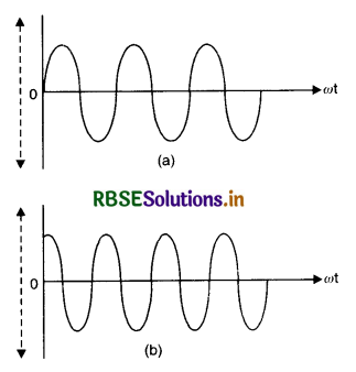
The instantaneous value of a.c. is given by
I = I0 sin ωt [Fig. LAQ 1 (a)] ...................... (I)
or I = I0 cos ωt [fig. LAQ 1 (b)] ...................(II)
where I0 is the peak value of a.c.
Similarly, the e.m.f. whose magnitude changes with time and direction reverses periodically is called alternating e.m.f.
The instantaneous alternating e.m.f. is given by
E = E0 sin ωt .................. (III)
or E = E0 cos ωt ................. (IV)
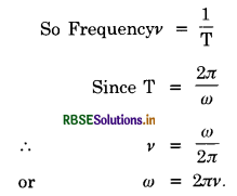
where ω = \(\frac{2 \pi}{T}\) is angular frequency.
Time period (T)
Time period is the time taken to complete one cycle.
Frequency (v)
Frequency is the number of cycles per second.
Amplitude (I0). Amplitude of alternating current is the peak value of alternating current and is denoted by I0.
Question 2.
Define mean value of alternating current and find relation between mean value and maximum value of alternating current.
Answer:
Mean value of alternating current.
The mean value of alternating current I = I0 sin ωt over a complete cycle is zero, because, the mean value for half periods are equal and alternately +ve and -ve and their sum for a complete cycle is zero. So we find average value over any half cycle.
Mean or average value of a.c. over any half cycle is that steady current (d.c.) which sends the same amount of charge in a circuit in a time equal to half the time period of a.c. (T/2) as is done by alternating current through the same circuit in the same time.
Expression for mean of a.c. (or Relation between mean value and peak value)
The instantaneous value of a.c. in a circuit is given by
I = I0 sin ωt ...................(1)
Let this current be passed through a circuit for a small time dt, then
Amount of charge passing through the circuit in time dt is given by
dq = Idt
Using Eq. (1), we get
dq = I0 sin ωt dt
Total charge q passing through the circuit in time T/2 is given by
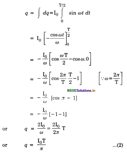
If Im is the mean value of a.c., then from the definition of mean value of current, we have
q = Im\(\frac{\mathrm{T}}{2}\) ...........................(3)
From Eq.(2) and (3), we have
Im\(\frac{\mathrm{T}}{2}\) = \(\frac{\mathrm{I}_0 \mathrm{~T}}{\pi}\)
or Im = \(\frac{2}{\pi}\)I0 = 0.637 I0
i.e. mean value of a.c. is 0.637 times (or 63.7%) of its peak value.
Question 3.
Define mean value of alternating e.m.f. and find relation between mean value and maximum value of alternating e.m.f.
Answer:
Mean value of alternating e.m.f.
Mean or average value of alternating e.m.f. over any half cycle in that steady (constant) e.m.f. which sends the same amount of charge in a circuit in a time equal to half the time period of alternating e.m.f. (\(\frac{\mathrm{T}}{2}\)) as is done by alternating e.m.f. through the same circuit in the same time.
Expression for mean value of alternating e.m.f. (Relation between mean value and peak value)
The instantaneous value of alternating e.m.f. in a circuit is given by
E = E0 sin ωt
So, alternating current at any instant will be
I = \(\frac{E}{R}=\frac{E_0}{R}\) sin ωt ..............................(1)
where R is the resistance of the circuit
Let this current be passed through a circuit for a small time dt, then
Amount of charge passing through the circuit in time dt is given by
dq = I dt
Using Eq. (1), we get
dq = \(\frac{\mathrm{E}_0}{\mathrm{R}}\) sin ωt dt.
Total charge q passing through the circuit in time \(\frac{\mathrm{T}}{2}\) is given by:
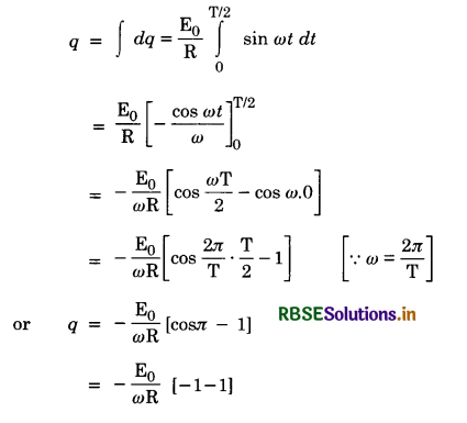
or q = \(\frac{2 \mathrm{E}_0}{\omega \mathrm{R}}=\frac{2 \mathrm{E}_0 \mathrm{~T}}{2 \pi \mathrm{R}}\)
or q = \(\frac{\mathrm{E}_0 \mathrm{~T}}{\pi \mathrm{R}}\) .............................(2)
If Em is the mean value of alternating e.m.f., then from definition of mean value of alternating e.m.f., we have
q = \(\frac{\mathrm{E}_{\mathrm{m}}}{\mathrm{R}} \frac{\mathrm{T}}{2}\) ...........................(3)
From Eq.(2) and (3), we have
\(\frac{\mathrm{E}_{\mathrm{m}} \mathrm{T}}{2 \mathrm{R}}=\frac{\mathrm{E}_0 \mathrm{~T}}{\pi \mathrm{R}}\)
or Em = \(\frac{2}{\pi}\)E0 = 0.637 E0
i.e. mean value of alternating e.m.f. is 0.637 (or 63.7%) of its peak value.
Question 4.
What is meant by root mean square value of alternating current? Derive an expression for r.m.s. value of alternating current.
Or
Define peak and root mean square value of alternating current. Derive an expression for the root mean square value of alternating current or voltage.
Answer:
Peak Value. Peak Value of a.c. is the maximum value of alternating current, denoted by I0.

Let I be instantaneous value of current at any instant t. This varies from 0 to I0, I0 to -I0 and -I0 to 0.
Root Mean Square Value of a.c.
[Irms = Ieff = Iv]
Root mean square value of a.c. is that steady current; which would produce the same amount of heat in a given resistance in a given time as is done by a.c. when passed through the same resistance for the same time. It is also called effective or virtual value of a.c.
Expression for virtual value of current (Relation between virtual and peak value)
The instantaneous value of alternating current is given by
I = I0 sin ωt ....................(1)
Let this current be passed through a resistance R for a small time dt.
The heat produced dH is given by
dH = I2 Rdt = RI2di
Using Eq. (1), we get
dH = RI02 sin2 ωt dt
Total heat produced when the current is passed for time T (say) can be obtained by integrating the above equation within the limits t = 0 and t = T.
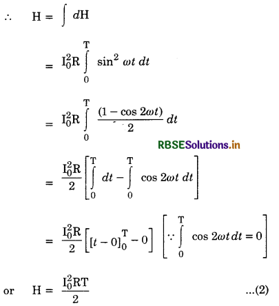
If Iv is the virtual (or rms) value of a.c., then by definition of virtual current, we have
H = Iv2 RT ........................(3)
From Eq.(2) and (3), we get
Iv2 RT = \(\frac{\mathrm{I}_0^2 \mathrm{RT}}{2}\)
or Iv = \(\frac{\mathrm{I}_0}{\sqrt{2}}\) = 0.707 I0
or Iv = 0.707 I0
i.e. Virtual value of alternating current is 0.707 times (or 70.7%) of its peak value.
Question 5.
What is root mean square value of alternating e.m.f.? Derive expression for it.
Answer:
Root Mean Square Value of alternating e.m.f.
Root mean square value of alternating e.m.f. is that steady voltage; which would produce the same amount of heat in a given resistance in a given time as is done by alternating e.m.f. when passed through the same resistance for the same time.
Expression for virtual value of e.m.f. (Relation between virtual value and peak value)
The instantaneous value of alternating e.m.f. is given by
E = E0 sin ωt
So, alternating current at any instant will be
I = \(\frac{E}{R}=\frac{E_0}{R}\) sin ωt ...................(1)
Let this current be passed through a resistance R for a small time dt
The heat produced d H is given by
dH = I2 Rdt = \(\frac{\mathrm{E}^2}{\mathrm{R}^2}\) Rdt = \(\frac{\mathrm{E}^2}{\mathrm{R}}\) dt
or dH = \(\frac{\mathrm{E}_0^2}{\mathrm{R}}\) sin2 ωt dt
Total heat produced when the current is passed for time T (say) can be obtained by integrating the above equation within the limits t = 0 and t = T.
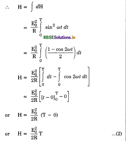
If Ev is virtual (or rms) value of alternating e.m.f. then by definition of virtual e.m.f., we have
H = \(\frac{\mathrm{E}_v^2}{\mathrm{R}}\)T ..........................(3)
Eq. (2) and (3), we have
\(\frac{\mathrm{E}_v^2}{\mathrm{R}}\)T = \(\frac{\mathrm{E}_0^2}{2 \mathrm{R}}\)T
or Ev = \(\frac{\mathrm{E}_0}{\sqrt{2}}\) = 0.707 E0
i.e. Virtual value of alternating emf is 0.707 times (or 70.7%) of its peak value.
Question 6.
What do you mean by phasor and phasor diagram? Explain.
Answer:
Phasor A phasor may be defined as a quantity which varies periodically with time and is represented as the projection of a rotating vector.
In d.c. supply the e.m.f. and current are always in same phase but in a.c. circuit having a resistor R or an inductor L or a capacitor C or any combination of these circuit elements, it is found that although the e.m.f. and current have the same frequency, yet they may be out of phase with each other i.e. the peak value of current may not occur, at the same time. This brings the idea of ‘lag’ or ‘lead’ in a.c. circuit.
Let instantaneous value of alternating e.m.f. be given by
E = E0 sin ωt ............................(1)
and I = I0 sin (ωt - Φ) ....................(2)
where Φ is the angle between E and I. (Here the current is said to be lagging behind e.m.f. by a phase Φ)
Here E and I may be considered to be the projections of E0 and I0 respectively. Such alternating e.m.f. and currents are called phasors. Angle between these phasors, represents the phase difference between applied alternating e.m.f. and current flowing through the circuit.
Phasor diagram
Diagram which represents alternating e.m.f. and currents (having the same frequency) on the rotating vectors along with phase angle between them is called a phasor diagram.
In order to draw a phasor diagram of alternating e.m.f. and current as given in Eq. 1 & 2. Let us draw two circles having radii E0 and I0 respresented by rotating vectors \(\overrightarrow{\mathrm{OP}}\) and \(\overrightarrow{\mathrm{OQ}}\) respectively Fig. LAQ 6 (a). The projection of E0 is E and I0 is I represent the phasor (i.e. instantaneous value of alternating e.m.f. and current respectively) and Φ represents the phase angle by which phasor I lags behind phasor E.
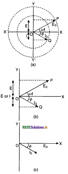
Thus Fig. LAQ 6 (a) is a phasor diagram. Fig. LAQ 6 (b) is also a phasor diagram of alternating, e.m.f. and current drawn in a simple way and we can also draw phasor diagram by Fig. LAQ 6 (c) if we are interested only in phase relationship.
Question 7.
Show that current and voltage are in phase when an a.c. source is connected to a pure resistor.
Answer:
Let us consider a pure resistor R connected to an alternating source of e.m.f. E as shown in Fig. LAQ 7 (a).
Let instantaneous value of alternating e.m.f. be given by
E = E0 sin ωt .................................(1)
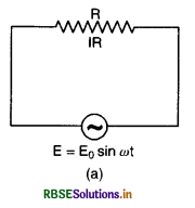
If I is the current in the circuit at any time t, then
I = \(\frac{E}{R}=\frac{E_0}{R}\) sin ωt = I0 sin ωt
or I = I0 sin ωt ........................(2)
where I0 = \(\frac{\mathrm{E}_0}{\mathrm{R}}\) is the peak value of alternating current.
From Eqs. (1) & (2), we find that current and e.m.f. are in same phase, when a.c. is passed through a pure resistor. Fig. LAQ 7 (b) is the graphical representation of E and I and we find that both current and e.m.f. start from zero at the same time, reach maxima at the same time and have same sinusoidal shape.
Fig. LAQ (c) is the phasor diagram representing the phase relationship between alternating e.m.f. and current.
Question 8.
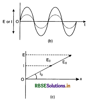
Show mathematically that in an a.c. circuit containing only inductance, the current lags behind the e.m.f. by a phase of π/2.
An a.c. voltage E = E0 sin ωt is applied across an inductor L. Obtain an expression for current I.
Answer:
Let us consider an inductor of inductance L connected to a source of alternating e.m.f. E as shown in Fig. LAQ 8 (a).
Let instantaneous value of alternating e.m.f. be given by
E = E0 sin ωt .............................(1)
In an inductor, instantaneous e.m.f. induced in the inductor is given by:
E = L\(\frac{d \mathrm{I}}{d t}\)
or dI = \(\frac{E}{L}\)dt
Using Eq. (1) we get
dI = \(\frac{\mathrm{E}_0}{\mathrm{~L}}\) sin ωt
Integrating both sides, we get
I = ∫dI = \(\frac{\mathrm{E}_0}{\mathrm{~L}}\) ∫ sin ωt dt
= -\(\frac{\mathrm{E}_0}{\omega \mathrm{L}}\) cos ωt
or I = -I0 cos ωt .............................(2)
where I0 = \(\frac{\mathrm{E}_0}{\omega \mathrm{L}}\) is the peak value of alternating current and ωL is the resistance offered by the inductor and is called inductive reactance denoted by XL (= ωL).
Eq.(2) can be written as
I = I0 sin (ωt - \(\frac{\pi}{2}\)) ...........................(3)
From equations (1) and (2), we find that the current lags behind the e.m.f. by a phase \(\frac{\pi}{2}\). Fig. LAQ 8(b) is the graphical representation of time variation of E and I.
Fig.LAQ 8(c) is the phasor diagram representing the phase relationship between alternating e.m.f. and current.
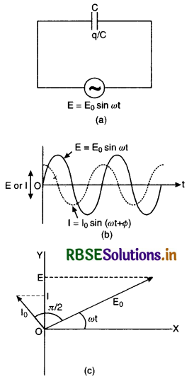
Question 9.
Show mathematically that in an a.c. circuit only containing capacitance, the current leads e.m.f. by a phase angle π/2.
Answer:
Let a capacitor of capacitance C be connected to an alternating source as shown in Fig. LAQ 9 (a).
Let instantaneous alternating e.m.f. be given by
E = E0 sin ωt ...............................(1)
If I and q are current and charge in the circuit at any time t, then
Instantaneous e.m.f. across the capacitor
E = \(\frac{q}{C}\)
or q = CE
Using Eq. (1). we get
q = CE0 sin ωt
The instantaneous current is the rate of growth of charge on the capacitor
So I = \(\frac{d q}{d t}=\frac{d}{d t}\)(CE0 sin ωt)
= CE0 \(\frac{d}{d t}\) sin ωt
= ω CE0 cos ωt
= \(\frac{\mathrm{E}_0}{1 / \omega \mathrm{C}}\) cos ωt
or I = I0 cos ωt .................................(2)
where I0 = \(\frac{\mathrm{E}_0}{1 / \omega \mathrm{C}}\) is the peak value of a.c. and \(\frac{1}{\omega \mathrm{C}}\) is the resistance offered by the capacitor and is called capacitive reactance denoted by XC(=\(\frac{1}{\omega \mathrm{C}}\))
Eq.(2) can be written as
I = I0 sin (ωt + \(\frac{\pi}{2}\)) .....................................(3)
From Eq.(2) and (3), we find that the current leads the e.m.f. by a phase \(\frac{\pi}{2}\). Fig. LAQ 9(b) is the graphical representation of time variation of E and I.
Fig. LAQ 9(c) is the phasor diagram representing the phase relationship between alternating e.m.f. and current.
Question 10.
Establish the phase relation between voltage and current in an a.c. circuit containing resistance R and inductance L and determine the impedance of LR circuit.
Answer:
Let an inductance L and resistance R be connected in series to a source of an alternating e.m.f. E as shown in Fig. LAQ 10 (a).
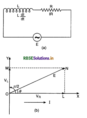
The alternating current I at all points in series circuit has the same amplitude and phase but the voltage across each element will be of different amplitude and phase.
(i) If VR is the voltage across R, then
VR= IR
Voltage across the resistor is in phase with current
(ii) If VL is the voltage across, then
VL = I XL
Voltage across the inductor leads the current by a phase π/2.
Let us construct the phasor diagram for this circuit. A single phasor I is used to represent the current in each element and VR and VL represent voltage phasors. If VR is represented along OX by OL, (current is also along OX) then VL will be along OY by OM because VL leads the current I by a phase π/2. This is graphically represented in Fig. LAQ 10 (b).The resultant of VR and VR is represented by E and makes an angle Φ with current I.
From the phasor diagram, we find that
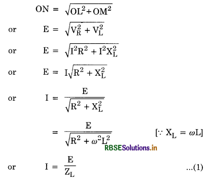
where ZL = \(\sqrt{\mathrm{R}^2+\omega^2 \mathrm{~L}^2}\) is the effective opposition offered by L and R and is called impedance of LR circuit . Since Φ is the angle made by the resultant of VR and VR with X-axis, so from phasor diagram, we have
tan Φ = \(\frac{\mathrm{LN}}{\mathrm{OL}}=\frac{\mathrm{OM}}{\mathrm{OL}}=\frac{\mathrm{V}_{\mathrm{L}}}{\mathrm{V}_{\mathrm{R}}}\)
= \(\frac{\mathrm{IX}_{\mathrm{L}}}{\mathrm{IR}}\)
= \(\frac{\mathrm{X}_{\mathrm{L}}}{\mathrm{R}}=\frac{\omega \mathrm{L}}{\mathrm{R}}\)
or tan Φ = \(\frac{\omega \mathrm{L}}{\mathrm{R}}\) .....................................(2)
Equation (2) gives the phase angle Φ, by which alternating e.m.f. (voltage) leads the current in an LR-circuit.
Question 11.
Establish the phase relation between voltage and current in an a.c. circuit containing capacitance C and resistance R and determine the impedance of C-R circuit.
Answer:
Let a capacitor of capacitance C and a resistance R be connected in series to a source of an alternating e.m.f. E as shown in Fig.LAQ 11 (a).
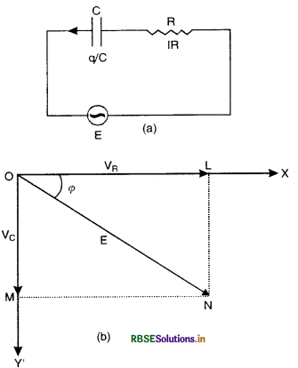
The alternating current I at all points in the circuit has the same amplitude and phase, but the voltage across each element will be of different amplitude and phase.
(i) If VR is the voltage across R, then
VR = IR
Voltage across the the resistor is in phase with current.
(ii) If VL is the voltage across C, then
VC = IXC
Voltage across the capacitor lags behind the current by a phase π/2.
Let us construct the phasor diagram for this circuit. A single phasor I is used to represent the current in each element and VR and VC represent voltage phasor. If VR is represented along OX by OL (current is also along OX) then, VC will be represented along OY' by OM because VC lags behind I by a phase π/2. This is graphically represented in Fig. (b). The resultant of VR and VC is represented by E and makes an angle Φ with current I
From the phasor diagram, we find that
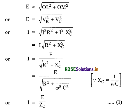
where ZC = \(\sqrt{\mathrm{R}^2+1 / \omega^2 \mathrm{C}^2}\) is the effective opposition offered by C and R and is called impedance of CR circuit.
Since Φ is the angle made by the resultant of VC and R with x-axis so from phasor diagram, we have
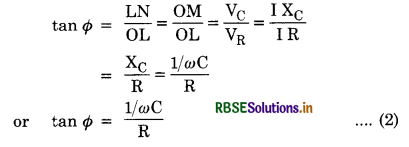
Eq. (2) gives the phase angle Φ by which alternating e.m.f. (voltage) lags behind the current in a CR circuit.
Question 12.
Derive a relation for the impedance of LCR-circuit. What is the relationship between the current and e.m.f. in LCR circuit?
Answer:
Let an inductance L, capacitance C and resistance R be connected in series to an alternating source of e.m.f. E as shown in Fig.LAQ 12(a).
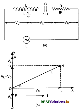
The alternating current at all points in a series circuit has the same amplitude and phase, but the voltage across each element will be of different amplitude and phase.
(i) If VR is the voltage across R, then
VR = IR
The voltage across the resistor in the phase with current.
(ii) If VL is the voltage across L, then
VL = I XL
The voltage across the inductor leads the current by a phase π/2.
(iii) If VC is the voltage across C, then
VC = IXC
The voltage across the inductor lags behind the current by a phase π/2.
Let us construct the phasor diagram for this circuit. A single phasor I is used to represent the current in each element and VR, VL and VC represent voltage phasors.
If VR is represented along OX by OL (current along OX), VL and VC will be perpendicular to x-axis. Let VL acts along Y-axis and represented by OM and VC acts along Y'-axis and represented by OP. So VL and VC all acting along the same line but in opposite directions. If VL > VC, then (VL - VC) is along VL represented by OQ and perpendicular to phasor VR as shown in Fig. LAQ 12 (b). The sum of VR, VL and VC equal to E and makes an angle Φ with the current I
From the phasor diagram, we find that

where Z = \(\sqrt{\mathrm{R}^2+\left(\omega \mathrm{L}-\frac{1}{\omega \mathrm{C}}\right)^2}\) is the effective opposition offered by L, C and R and is called the impedance of LCR-circuit.
Since Φ is the angle made by the resultant of (VR - VC) and R with x-axis, so from phasor diagram, we have:

Now three cases are of interest:
(i) If ωL > 1/ωC i.e. the circuit is inductive dominant circuit and tan Φ is +ve, so the current will lag behind e.m.f. by a phase Φ.
(ii) If ωL < 1/ωC i.e. the circuit is capacitive dominant circuit and tan θ is -ve, so the current will lead the e.m.f. by a phase Φ.
(iii) If ωL = 1/ωC then tan Φ = 0 or Φ = 0 i.e. the current and e.m.f. will be in phase and the circuit is said to be in resonance.
Question 13.
Derive an expression for frequency of series resonance circuit. Where this circuit is used?
Answer:
Consider a circuit consisting of an inductance L, capacitance C and a resistance R, all connected in series to an alternating source of e.m.f. E as shown in Fig. LAQ 13 (a).
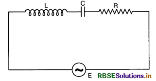
The impedance of LCR circuit is given by
Z = \(\sqrt{\mathrm{R}^2+\left(\omega \mathrm{L}-\frac{1}{\omega \mathrm{C}}\right)^2}\)
The instantaneous value of current in this circuit is given by
I = \(\frac{E}{Z}=\frac{E_v}{\sqrt{\mathrm{R}^2+\left(\omega \mathrm{L}-\frac{1}{\omega \mathrm{C}}\right)^2}}\)
If ω is very large (i.e. ω → ∞), then (ωL - \(\frac{1}{\omega \mathrm{C}}\))2 becomes very large, and hence Z becomes large. so I in the circuit is low.
If ω is very small (i.e. ω → 0) then (ωL - \(\frac{1}{\omega \mathrm{C}}\))2 again becomes very large and hence Z should be small i.e. \( \sqrt{\mathrm{R}^2+\left(\omega \mathrm{L}-\frac{1}{\omega \mathrm{C}}\right)^2}\) is minimum.
This is possible, if
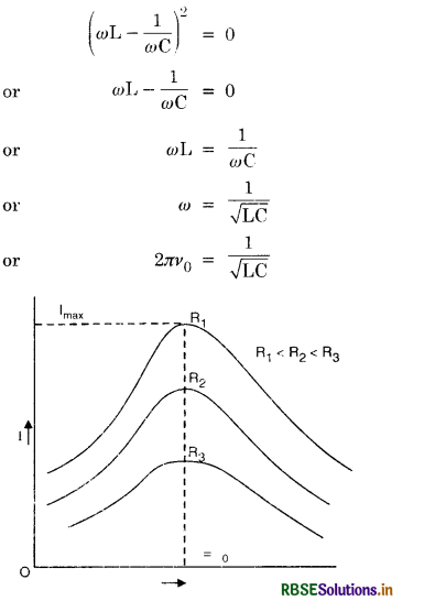
or v0 = \(\frac{1}{2 \pi \sqrt{\mathrm{LC}}}\)
where v0 is the frequecny of a.c. when current is maximum called resonance frequency.
The maximum value of current will be
Imax = \(\frac{\mathbf{E}_0}{\mathrm{R}}\)
A graph between I and for different values of R is as shown in Fig. LAQ 13 (b). From the graph we find that the resonance frequency is independent of resistance but the sharpness of the resonance increases with the decrease in the value of R.
Uses: LCR series resonant circuits are used in radio and T.V. receivers to select the desired frequency.
Question 14.
Derive expression for frequency of parallel resonance circuit. Where this circuit is used?
Answer:
Consider a circuit consisting of an inductance L and a capacitance C, both connected in parallel with an alternating source of e.m.f., E as shown in Fig. LAQ 14 (a).
The instantaneous value of alternating e.m.f. is given by
E = E0 sin ωt .......................(1)
Let IL. be current passing through the inductor. Since current in an inductor lags behind the e.m.f. by a phase π/2.
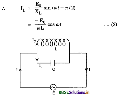
Let IC be current passing through the capacitor. Since current in a capacitor leads the e.m.f. by a phase π/2,
∴ IC = \(\frac{\mathrm{E}_0}{\mathrm{X}_{\mathrm{C}}}\) sin (ωt - π/2)
= E0 ωC cos ωt .............................(3)
∴ Total current I in the circuit at any instant will be
I = IL + IC
= E0\(\left(-\frac{1}{\omega L}+\omega \mathrm{C}\right)\). cos ωt
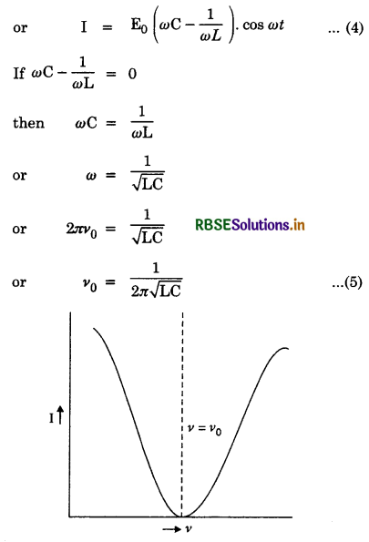
Thus we find that in parallel resonant circuit, resonance occurs when the applied frequency becomes equal to natural frequency of oscillation of the circuit.
From eq. (4), we find that at parallel resonance, the current in the circuit becomes zero i.e. I = 0 (Fig. LAQ 14) and the impedance becomes maximum. Due to this reason the circuit is called rejected circuit and work as perfect-choke for a.c. Fig. LAQ 14 (b) shows the variation of current with the frequency.
Uses: These circuits are used as filter circuits in radio to block the currents of undesirable frequencies and is also called oscillatory circuit.
Question 15.
What do you mean by quality factor or Q value of resonance circuit?
Answer:
Quality factor
The quality factor of LCR-circuit is the ratio of the potential difference across inductance (or capacitance) at resonance to the applied voltage. This is also called the figure of merit or quality ratio or Q-value of LCR series circuit
i.e. Q = \(\frac{\text { Voltage across }(\mathrm{L} \text { or } \mathrm{C})}{\text { Voltage applied }}\)
At resonance
Voltage across L = IXL
Voltage across C = IXC
Voltage applied = Voltage drop across R = IR
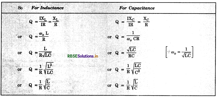
Thus quality factor, Q = \(\frac{1}{\mathrm{R}} \sqrt{\frac{\mathrm{L}}{\mathrm{C}}}\)
So the quality factor in a series LCR circuit has high value if:
(i) Value of R is small
(ii) Value of \(\frac{\mathrm{L}}{\mathrm{C}}\) is high.
Question 16.
Derive an expression for energy stored in an inductor and show that the work done during growth of current is returned back to the source during decay of current.
Answer:
Energy stored in an inductor
Consider an inductor of inductance L. Let I be instantaneous current in the inductor and dI/dt is the rate of growth of current.
Induced e.m.f., E = L\(\frac{d \mathrm{I}}{d t}\) (in magnitude)
If the source sends a charge dq in time dt, then dq = Idt
Small amount of work done by the source dW = E dq
= E I dt = L\(\frac{d \mathrm{I}}{d t}\). I dt
or dW = LI dI
Total work done during growth of current in an inductor by the external source
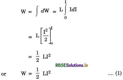
This work done is stored in the form of magnetic energy.
With an a.c.
This energy stored in the inductor is returned back during the decay of current from I to 0.
Total work done during whole cycle of a.c.
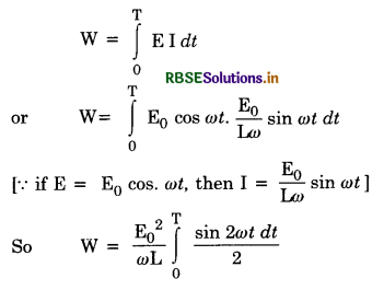
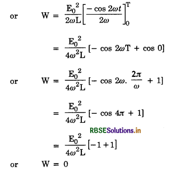
Question 17.
Derive an expression for energy stored in a capacitor and show that net energy stored in the capacitor during whole cycle of a.c. is zero.
Answer:
Energy stored in a capacitor
Consider a capacitor of capacitance C. Let q be charge and V be potential difference across the plates of the capacitor at any instant during charge.
∴ V = \(\frac{q}{C}\)
If the source sends an addition charge dq, then
Work done in giving it an additionl instalment dq of charge i.e.
dW = V. dq
∴ Total work done in charging the capacitor from q = 0 to q = q
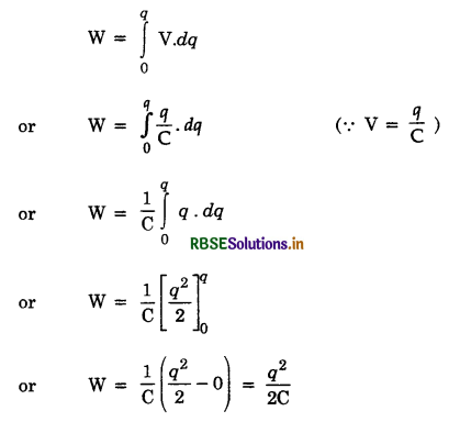
This work done is equal to the electric energy (U) stored in the capacitor.
U = \(\frac{1}{2} \frac{\mathrm{C}^2 \mathrm{~V}^2}{\mathrm{C}}\) [∵ q = CV]
or U = \(\frac{1}{2}\)CV2
This energy is stored in the form of electric potential energy.
It is this energy which is returned during discharge.
With an a.c. When the capacitor is across an a.c. source, it is being charged during half the cycle and discharged during rest.
Total work during whole cycle of a.c.
Question 18.
Show that when capacitor is discharged through an inductor the electrical oscillations are produced (LC - oscillations). Find the frequency of oscillations.
Answer:
LC oscillations. If a charged capacitor is allowed to discharge through an inductance with negligible resistance the current will not stop even when the capacitor is completely discharged but continue charging the capacitor in the opposite direction. The capacitor then discharges again sending current in opposite direction to the first. The current surges back and forth in the circuit.
The surging backward and forward of electric current through LC circuit is called electrical oscillations.
When a capacitor is charged, the energy is stored in the form of electric field [Fig. LAQ 18 (a)]. When the inductor is connected to this charged capacitor, the capacitor sends current and produces growing magnetic field inside the conductor. When the capacitor is fully discharged the energy is stored in the form of magnetic field [Fig. LAQ 18 (b)].
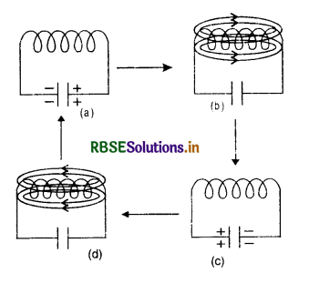
Now the magnetc flux linked with the inductance starts decreasing and induced e.m.f. is produced which charges the capacitor with opposite polarity and again the energy is stored in the form of electric field [Fig. LAQ 18 (c)].
The capacitor will again discharge by sending current in opposite direction and produces magnetic flux in the inductor in opposite direction till it becomes fully discharged. [Fig LAQ 18 (d)]. Now the magnetic flux linked with inductance start decreasing and induced e.m.f. produced charges the capacitor plates with polarity opposite to that in previous case. i.e. same as in Fig. LAQ 18 (a). The whole process is then repeated again and again and then electrical oscillations are produced.
If the current has no resistance, no loss of energy would occur and the process will be repeated continuously and electro-magnetic waves of constant amplitude will be produced as shown in Fig. LAQ 18 (e). These are called undamped oscillations.
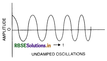
In actual practice, however, there do occur some losses of energy due to finite resistance of the circuit and the amplitude of oscillations goes on decreasing. These are called damped oscillations as shown in Fig. LAQ 18 (f).
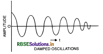
To obtain undamped oscillations, the energy loss is duly compensated by some arrangement e.g. transistor etc.
The frequency of oscillations is given by
v = \(\frac{1}{2 \pi \sqrt{L C}}\)
Expression for frequency (or Analytical treatment of LC-oscillations)
Let capacitance of a capacitor = C
Inductance of an inductor = L
Let the capacitor be charged to its maximum value q0 at t = 0
∴ at t = 0, q = q0 and I= 0
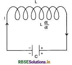
Now the charged capacitor is connected to the inductor as shown in the figure. The capacitor starts discharging and induced e.m.f. is produced in the inductor.
Let charge on the capacitor at time, t = q
Current in the circuit at time t = I
Rate of charge of current =\( \frac{d q}{d t}\)
Potential difference across the inductor at time, t = -L\(\frac{d \mathrm{I}}{d t}\)
Potential difference across the capacitor at time, t = q/C.
∴ In LC-circuit, at any instant, we have
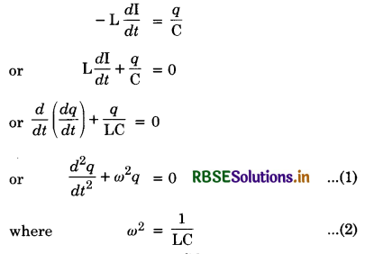
Equation (1) represents S.H.M.
The solution of this equation is given by
q = A cos ωt + B sin ωt ...................(3)
where A and B are constants which are to be determined by using boundary conditions which are
(i) At t = 0, q = q0
So Eq. (3) becomes
q0 = A cos 0° + B sin 0°
q0 = A
or A = q0 ............................(4)
Current in the circuit at any instant is given by
I = \(\frac{d q}{d t}\)
= \(\frac{d}{d t}\) [A cos ωt + B sin ωt]
= A(-sin ωt) ω + B (cos ωt)ω
or I = -Aω sin ωt + Bω cos ωt ...............................(5)
(ii) At t = 0, I = 0
So Eq. (5) becomes
0 = -A ω sin 0° + B ω cos 0°
or 0 = B ω
or B = 0 .....................(6)
Putting the value of A and B in Eq. (3), we get
q = q0 cos ωt .......................(7)
From Eq. (7), we find that the charge on the capacitor is harmonic function of time and hence keeps on oscillating.
From Eq. (2), we have
ω2 = \(\frac{1}{\mathrm{LC}}\)
or ω = \(\frac{1}{\sqrt{\mathrm{LC}}}\)
If v is the frequency of oscillation, then
2πv = \(\frac{1}{\sqrt{\mathrm{LC}}}\)
or v = \(\frac{1}{2 \pi \sqrt{\mathrm{LC}}}\)
Question 19.
Show that the energy in LC-Oscillations is always constant (i.e. conserved).
Answer:
In LC circuit the total energy is the sum of energy stored in the capacitor and in the inductor at any instant.
At t = 0
Let q0 be initial charge on the capacitor of capacitance C.
∴ Electrostatic energy stored in the capacitor
Uc0 = \(\frac{q_0^2}{2 C}\)
Magnetic field energy in the inductor
Um0 = \(\frac{1}{2}\)LI2 = 0 [∵ L = 0]
∴ Total energy in the circuit.
UT = Uc0 + Um0 = \(\frac{q_0^2}{2 C}\) + 0
UT = \(\frac{q^2}{2 C}\) ........................(1)
At any time t > 0
After connecting charged capacitor with the inductor, the capacitor starts discharging through inductor. If q is the charge in the capacitor at any time t(q < q0).
The electrostatic energy in the capacitor
UC = \(\frac{q^2}{2 C}=\frac{q_0^2}{2 \mathrm{C}}\) cos2 ωt ...................................(2)
[∵ q = q0 cos ωt]
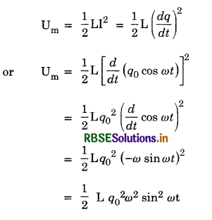
or Um = \(\frac{1}{2}\)Lq02 \(\frac{1}{\mathrm{LC}}\) sin2 ωt [∵ ω2 = \(\frac{1}{\mathrm{LC}}\)]
or Um = \( \frac{q_0^2}{2 C}\) sin2 ωt ...........................(3)
∴ At time t, total energy in the circuit
Uc + Um = \(\frac{q_0^2}{2 C}\) cos2 ωt + \(\frac{q_0^2}{2 C}\) sin2 ωt
= \(\frac{q_0^2}{2 C}\) [cos2 ωt + sin2 ωt]
= \(\frac{q_0^2}{2 C}\)
Uc + Um = UT
Hence total energy in the LC oscillations is always constant i.e. conserved and is simply exchanged between the capacitor and the inductor.
Question 20.
Derive an expression for average power in an A.C. circuit containing resistor only.
Answer:
Power is the rate of doing work. In A.C. current and voltage change at every moment. Since power is the product of instantaneous voltage and current, therefore it changes at every moment.
To determine average power in a circuit containing pure resistor, determine total energy spent in one cycle and divide it by the time period.
Instantaneous power
= EI = [E0 sin ωt] [ I0 sin ωt]
Instantaneous work done in small interval dt is
dW = EI dt = E0I0 sin2 ωt dt
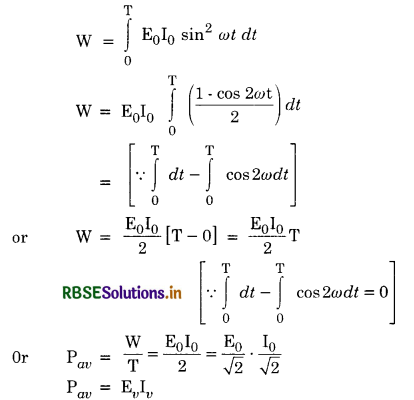
∴ Average power over a complete cycle of a.c. through a resistor is the product of virtual voltage and virtual current.
Question 21.
Obtain an expression for the power in a.c. circuit containing a resistance and capacitance in series.
Answer:
Average power in CR-circuit
Let alternating e.m.f. applied to CR circuit be
E = E0 sin ωt
Let alternating current developed, leads the applied e.m.f. by Φ then
I = I0 sin (ωt + Φ)
∴ Instantaneous power,
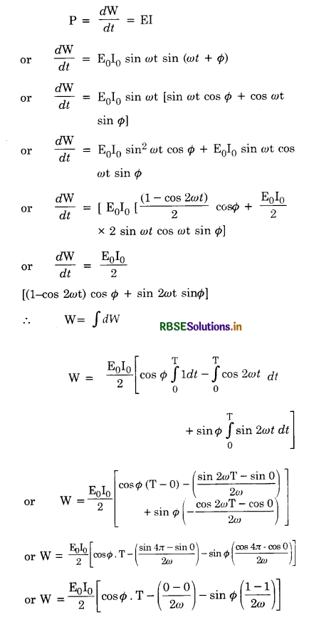
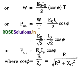
Question 22.
Derive an expression for electric power in an LCR a.c. series circuit.
Answer:
Let E be alternating e.m.f. applied to an LCR circuit and is given by
E = E0 sin ωt
If a.c. lags behind the applied e.m.f. by Φ, then
I = I0 sin (ωt - Φ)
Instantaneous power,
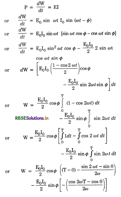
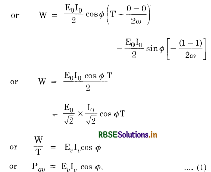
or Average power = Apparent power x power factor
Average power is also called true power.
∴ True power = Apparent power x power factor
∴ Power factor = cos Φ
= \(\frac{\text { True power }}{\text { Apparent power }}\) ...................................(2)
In practie, the true power is expressed in kilowatt (kW) and apparent power in kilowatt ampere (kVA).
Special cases
(i) If a.c. circuit contains only resistance (R)
Here Φ = 0, so cos Φ = cos 0° = 1
∴ Pav = EvIv cos 0°
or Pav = EvIv
(ii) If a.c. circuit contains only pure inductance (L)
Here Φ = π/2
So Pav = EvIv cos π/2 = 0 [∵ cos π/2 = 0]
i.e. Average power consumed in pure inductive circuit in a.c. is zero.
(iii) If a.c. circuit contains pure capacitance (C)
Here Φ = -π/2
∴ Pav = EvIv cos (-π/2) = 0 [∵ cos -π/2 = -cos π/2 = 0]
i.e. Average power consumed in pure capacitive circuit in a.c. is zero.
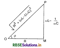
(iv) If a.c. circuit contains LCR circuit
Here
tan Φ = \(\frac{\omega \mathrm{L}-\frac{1}{\omega \mathrm{C}}}{\mathrm{R}}\)
From the figure, we have
cos Φ = \(\frac{\mathrm{R}}{\sqrt{\mathrm{R}^2+\left(\omega \mathrm{L}-\frac{1}{\omega \mathrm{C}}\right)^2}}=\frac{\mathrm{R}}{\mathrm{Z}}\) ................................(3)
where Z = \(\sqrt{\mathrm{R}^2+\left(\omega \mathrm{L}-\frac{1}{\omega \mathrm{C}}\right)^2}\) ....................................(4)
Z is the impedence of LCR circuit
∴ Pav = EvIv cos Φ = \(\frac{\mathrm{E}_v \mathrm{I}_v \mathrm{R}}{\mathrm{Z}}\)
or Pav = \(\frac{\mathrm{E}_v^2 \mathrm{R}}{\mathrm{Z}^2}\) [∵ Iv = \(\frac{\mathrm{E}_v}{\mathrm{Z}}\)]
or Pav = \(\frac{\mathrm{E}_r{ }^2 \mathrm{R}}{\mathrm{R}^2+\left(\omega \mathrm{L}-\frac{1}{\omega \mathrm{C}}\right)^2}\)
Question 23.
What is a choke coil? Discuss its use in a.c. circuits?
Answer:
Choke coil
A choke coil is simply an inductor with large value of self-inductance.
The choke coil consists of a large number of turns of thick copper wire bound closely over a laminated soft iron core. The inductive reactance offered by the coil is XL = ωL becomes large. Therefore, magnitude of a.c. is reduced.
In an ideal choke coil, ohmic resistance = 0. Therefore, no electrical energy/power is wasted. A phase angle of π/2 is introduced between current and voltage through an ideal inductor.
∴ Average power over a complete cycle is
P = EvIv cos Φ = EvIv cos 90°
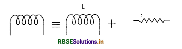
However, in actual practice, a choke coil of inductance L is linked with a small resistance r. It may be treated as a series combination of L and r. [Fig. LAQ 23b]. Therefore, average power consumed over a complete cycle in the practical choke coil is
P = Ev Iv cos Φ
or P= EvIv\(\frac{r}{\sqrt{r^2+\omega^2 L^2}}\)
In practice, a low frequency choke is made of insulated copper wire wound over a soft iron core [laminated] called low frequency choke or audio frequency choke Fig. LAQ 23(c) and a high frequency choke has air as core material [Fig. LAQ 23(b)] to eliminated eddy current losses. High frequency chokes are also called radiofrequency chokes.
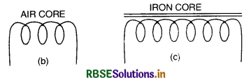
Air is used as core material because, the virtual value of a.c. is given by
Iv = \(\frac{\mathrm{E}_v}{\omega \mathrm{L}}=\frac{\mathrm{E}_v}{2 \pi v \mathrm{~L}}\)
So as v is very high. so L should not be large. hence air cored choke is used.
Importance of choke coil over ohmic reistance
In running an arc lamp on a continuous current of 10A, about 40V are required. So that the effective resistance of the arc lamp from Ohm's law, R = \(\frac{\mathrm{V}}{\mathrm{I}}\) = \(\frac{40}{10}\) = 4 ohm. To get a current of 10 A from 220 V mains, the resistance to be included in series with the circuit is \(\frac{220-40}{10}\) = 18 ohm. By so doing, there will be wastage of power
I2R = 102 x 18 = 1800 watt
and useful power available in the arc = 102 x 4 = 400 watt.
So that, out of the total power of 2200 watt
(= VI = 220 x 10 supplied by the source AC generator), 1800 watt are wasted. Thus the use of a pure resistance to reduce current in a circuit involves huge wastage of power.
In case of AC supply, there is an alternative more economical method in which an inductance called choke, is introduced in series with the arc instead of resistance. Let L be the inductance and R be the resistance of the choke, then
\(\frac{\mathrm{I}_0}{\sqrt{2}}=\frac{\frac{\mathrm{E}_0}{\sqrt{2}}}{\sqrt{\omega^2 \mathrm{~L}^2+\mathrm{R}^2}}\)
and cos Φ = \(\frac{\mathrm{R}}{\sqrt{\omega^2 \mathrm{~L}^2+\mathrm{R}^2}}\)
In the above example \(\frac{\mathrm{I}_0}{\sqrt{2}}\) = 10A,
or 10 = \(\frac{220}{\sqrt{\omega^2 L^2+4^2}}\)
Squaring, we get
ω2L2 + 16 = 22 x 22 = 484
ω2L2 = 484 - 16 = 468
ωL = 21.63
Let v = 50 Hz
ωL = 2π x 50 L
= 100πL = 21.63
L = \(\frac{21.63}{100 \pi}\) = 0.06887 H
Total Power = \(\frac{\mathrm{I}_0}{\sqrt{2}} \times \frac{\sqrt{\mathrm{E}}_0}{\sqrt{2}} \cos \phi\)
= 10 x 220 x \(\frac{\mathrm{R}}{\sqrt{\mathrm{R}^2+\mathrm{L}^2 \omega^2}}\)
= 10 x 220 x \(\frac{4}{22}\) = 400 W
∴ The chief advantage of choke is that there is no wastage of power. The only energy wastage is due to Hysteresis loss in iron core of the choke. Since the reactance of an inductance is proportional to frequency choke usually has a space.
Question 24.
What is wattless current?
Answer:
Wattless current. If the average power consumed due to the flow of current in a circuit is zero, the current is said to be wattless or idle.
Since in a pure capacitance and pure inductance the power factor is zero, so average power consumed is zero. But in actual practice inductance and capacitance possess some resistance, so some power is always consumed.
In an LCR circuit average power consumed is given by
Pav = EvIv cos Φ
If Ev leads the current Iv by a phase Φ as shown in figure LAQ 24 then Iv can be resolved in two components
(i) Iv cos Φ along Ev
(ii) Iv sin Φ perpendicular to Ev.
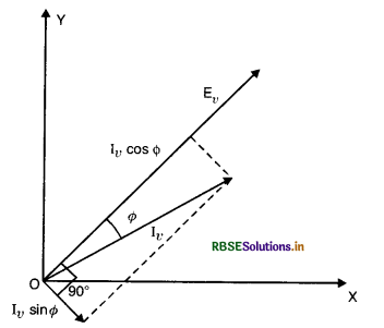
So Average power consumed due to component (Iv cos Φ) will be
P'av = Ev (Iv cos Φ). cos 0
= EvIv cos Φ
And Average power consumed due to component (Iv sin Φ) will be
P"av = Ev (Iv sin Φ) cos 90° = 0
Thus the energy is consumed by component (Iv cos Φ) and no energy is consumed by component (Iv sin Φ). Hence the component (Iv sin Φ) is called idle or wattless component, as it does not contribute to the power of the circuit. Greater the value of Iv sin Φ (or Φ), more is the wattless component of current.
The circuit in which electrical energy is consumed, we try to get as much wattless current as possible but those circuits which generate energy like electric generator, the wattless current is completely eliminated. This is done by using a capacitor having such a capacity that current and e.m.f. get in phase.
Question 25.
What is a generator or dynamo? Draw a labelled diagram of an a.c. generator. Give principle, construction and working of a.c. generator.
Answer:
Electric generator. A device which converts mechanical energy into electrical energy is called an electric generator or dynamo.
A.C. generator or A.C. dynamo
Principle. A.C. generator is based upon the phenomenon of electromagnetic induction i.e., whenever magnetic flux linked with a coil changes, an e.m.f. is induced in the coil.
Construction. It consists of the following essential parts:
1. Armature. It acts as a rotor. It consists of a large number of turns of insulated wires wound over a laminated soft iron core.
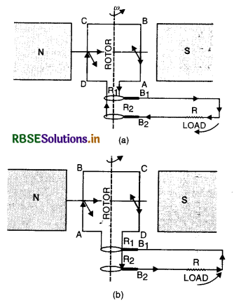
2. Magnet. Armature coil is rotated between pole pieces of a permanent (these days electromagnet) magnet.
3. Slip rings. AB is connected to the ring R1 and CD to ring R2. These rings rotate with the coil.
4. Brushes. B1 and B2 are two brushes or carbon rods. They are kept fixed and touch R1 and R2 lightly. The brushes are used to pass the current from armature coil to external load R.
Working. As armature coil rotates, the magnetic flux linked with the coil changes, hence induced e.m.f. is produced in the armature coil.
Let the armature ABCD is rotating in such a way that the arm AB moving upward and CD downward. By Flemings Right Hand Rule, we see that the induced current flows in the armature as shown in Fig. LAQ 25 (a).
By the time the armature turns through 180° (Fig. LAQ 25 b) with arm AB moving downward and CD moving upward, again applying Fleming’s Right Hand Rule, we find that the induced current flows in the armature as shown in Fig. LAQ 25 (b).
From Fig LAQ 25 (a) and LAQ 25 (b), we find that the directrion of induced e.m.f. and current in the external circuit is reversed after the armature has rotated through an angle 180°. Hence the current produced is alternating in nature
Theory. Let initially the coil is vertical i.e. θ = 0 at t = 0. Let at time t, if θ is angle through which it has rotated with angular velocity to ω (Fig. LAQ 25 (c, d))
So θ = ωt.
The magnetic flux linked with the coil.
Φ = n BA cos θ
or Φ = n BA cos ωt
Where n = number of turns of the coil
A = area enclosed‘by each turn of the coil
B = strength of magnetic field
θ = angle which the normal to the coil makes with \(\overrightarrow{\mathrm{B}}\) at any time t.
∴ Induced e.m.f.
E = -\(\frac{d \phi}{d t}=-\frac{d}{d t}\) (nBA cos ωt)
or E = -nBA \(\frac{d}{d t}\)(cos ωt)
E = nBA ω sin ωt. .............................(1)
E will be maximum if sin ωt = 1
If E0 is the maximum value of E, then
E0 = nBAω .........................(2)
Putting Eq.(2) in (1), we get
E = E0 sin ωt
or E = E0 sin θ ............................(3)

At θ = 0°, E = E0 sin 0 = 0
At θ = 90°, E = E0 sin 90 = E0
At θ = 180°, E = E0 sin 180° = 0
At θ = 270°, E = E0 sin 270° = -E0
At θ = 360°, E = E0 sin 360° = 0
If we plot a graph between θ and E, the graph is as shown in [Fig. LAQ 25 (d)]
Question 26.
Describe the principle, construction and working of a transformer. What are the energy losses in it?
Answer:
Transformer. A transformer is a device for converting a large alternating current at low voltage into a small alternating current at high voltage and vice-versa.
If the voltage is stepped up and the current is decreased, the transformer is called step up transformer and if the voltage is lowered and the current is increased, the transformer is called step down transformer.
Principle. It is based upon the principle of mutual inductance i.e. whenever magnetic flux linked with a coil is changed, an induced e.m.f. is produced in the neighbouring coil.
Construction. A transformer consists of two coils of insulated wire containing different number of turns wound separately on a continuous soft iron core as shown in Fig. LAQ 26. The coil to which the electric energy is fed is called the primary, whereas the coil from which the energy is drawn is called the secondary. The two coils of wire are close to each other but are not electrically connected. The entire magnetic flux coming out of one will practically remain in the iron core, and hence pass through the other coil. The soft iron core provides a good path for the magnetic lines of force and therefore, helps in making almost all of them pass through the secondary coil.

Action. Alternating current is fed to the primary. The alternating current in the primary produces an alternating magnetic flux in the core which passes through the secondary coil. Since magnetic flux remains practically confined within the core, the magnetic flux linked with the secondary is almost the same as that passing through the primary. The changing magnetic flux produces an induced e.m.f. in the secondary and also gives rise to self-induced (back) e.m.f. in the primary.
Consider the terminals of secondary coil to be open. Let Np and Ns be the number of turns in the primary and secondary coils respectively. Let Φ be the magnetic flux linked with the primary and the secondary at any instant. The induced e.m.f. in primary and secondary coils are given by:
Ep = -Np \(\frac{d \phi}{d t}\)
and Es = -Ns \(\frac{d \phi}{d t}\)
Thus \(\frac{\mathrm{E}_s}{\mathbf{E}_p}=\frac{\mathrm{N}_s}{\mathrm{~N}_p}\) ...........................(i)
The ratio of the number of turns in the secondary to that in the primary is called transformation ratio.
If a step up transformer, Ns > Np, i.e. the transformation ratio is greater than 1 so that Es > Ep.
In step down transformer, Ns < Np i.e., transformation ratio is less than 1. so that Es < Ep.
Output current. Further, according to the law of conservation of energy whether device is possible which can give any net gain of energy. Therefore, assuming no energy losses in the transformer, the energy drawn from the secondary is equal to that fed into the primary. Or, in other words,
Power output = Power input
If Ip and Is are the values of the currents in the primary and the secondary coils respectively, we have
Is Es = Ip Ep
or \(\frac{\mathrm{E}_s}{\mathrm{E}_p}=\frac{\mathrm{I}_p}{\mathrm{I}_s}\)
Thus as the voltage in the secondary increases, the current proportionately falls and vice versa i.e., whatever we gain in voltage, we stand to lose that much in current.
The efficiency of transformer is defined as
η = \(\frac{\text { Output power }}{\text { Input power }} \)
In an actual transformer, due to eddy currents in the core and also magnetic hysteresis of the core, part of the energy is actually lost.
Losses. Transformer is one of the most efficient machines known and its efficiency is high as 90-99%. It suffers from the following main losses
- Copper loss. Energy lost as heat produced in copper wire used in the winding when current is passed through them (given by I2R). This loss is minimized by using thick wire as their resistance is low.
- Iron loss. Energy lost due to eddy currents formed in the core. This can be eliminated by using laminated iron core.
- Hysteresis loss. It is the energy lost as work done in carrying the iron core through cycles of magnetization and demagnetization. This can be minimised by selecting iron with special magnetic properties to be used as core.
- Magnetic flux leakage. Due to imperfect insulation, some of the magnetic flux leaks and causes an energy loss.
- Humming loss. Due to passage of a.c. the core starts vibrating and produces humming sound. This sound production is called humming loss.
Uses
- Transformer is used in T.V., tape recorders, computers, air conditioners etc.
- In induction furnace.
- Step down transformer is used for welding purpose.
- Transformer is used for transmission of a.c. over long distances.
Question 27.
(a) Derive the relationship between peak and the rms value of current in an a.c. circuit.
(b) Describe briefly, with the help of a labelled diagram, working of a stepup transformer.
A step up transformer converts a low voltage into high voltage. Does it not violate the principle of conservation of energy? Explain.
Answer:
(a) Peak Value. Peak Value of a.c. is the maximum value of alternating current, denoted by I0.
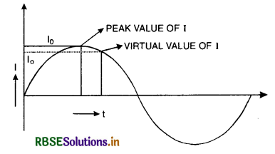
Let I be instantaneous value of current at any instant t. This varies from 0 to I0, I0 to -I0 and -I0 to 0.
Root Mean Square Value of a.c.
[Irms = Ieff = Iv]
Root mean square value of a.c. is that steady current; which would produce the same amount of heat in a given resistance in a given time as is done by a.c. when passed through the same resistance for the same time. It is also called effective or virtual value of a.c.
Expression for virtual value of current (Relation between virtual and peak value)
The instantaneous value of alternating current is given by
I = I0 sin ωt ....................(1)
Let this current be passed through a resistance R for a small time dt.
The heat produced dH is given by
dH = I2 Rdt = RI2di
Using Eq. (1), we get
dH = RI02 sin2 ωt dt
Total heat produced when the current is passed for time T (say) can be obtained by integrating the above equation within the limits t = 0 and t = T.

If Iv is the virtual (or rms) value of a.c., then by definition of virtual current, we have
H = Iv2 RT ........................(3)
From Eq.(2) and (3), we get
Iv2 RT = \(\frac{\mathrm{I}_0^2 \mathrm{RT}}{2}\)
or Iv = \(\frac{\mathrm{I}_0}{\sqrt{2}}\) = 0.707I0
or Iv = 0.707 I0
i.e. Virtual value of alternating current is 0.707 times (or 70.7%) of its peak value.
(b) Transformer. A transformer is a device for converting a large alternating current at low voltage into a small alternating current at high voltage and vice-versa.
If the voltage is stepped up and the current is decreased, the transformer is called step up transformer and if the voltage is lowered and the current is increased, the transformer is called step down transformer.
Principle. It is based upon the principle of mutual inductance i.e. whenever magnetic flux linked with a coil is changed, an induced e.m.f. is produced in the neighbouring coil.
Construction. A transformer consists of two coils of insulated wire containing different number of turns wound separately on a continuous soft iron core as shown in Fig. LAQ 26. The coil to which the electric energy is fed is called the primary, whereas the coil from which the energy is drawn is called the secondary. The two coils of wire are close to each other but are not electrically connected. The entire magnetic flux coming out of one will practically remain in the iron core, and hence pass through the other coil. The soft iron core provides a good path for the magnetic lines of force and therefore, helps in making almost all of them pass through the secondary coil.

Action. Alternating current is fed to the primary. The alternating current in the primary produces an alternating magnetic flux in the core which passes through the secondary coil. Since magnetic flux remains practically confined within the core, the magnetic flux linked with the secondary is almost the same as that passing through the primary. The changing magnetic flux produces an induced e.m.f. in the secondary and also gives rise to self-induced (back) e.m.f. in the primary.
Consider the terminals of secondary coil to be open. Let Np and Ns be the number of turns in the primary and secondary coils respectively. Let Φ be the magnetic flux linked with the primary and the secondary at any instant. The induced e.m.f. in primary and secondary coils are given by:
Ep = -Np \(\frac{d \phi}{d t}\)
and Es = -Ns \(\frac{d \phi}{d t}\)
Thus \(\frac{\mathrm{E}_s}{\mathbf{E}_p}=\frac{\mathrm{N}_s}{\mathrm{~N}_p}\) ...........................(i)
The ratio of the number of turns in the secondary to that in the primary is called transformation ratio.
If a step up transformer, Ns > Np, i.e. the transformation ratio is greater than 1 so that Es > Ep.
In step down transformer, Ns < Np i.e., transformation ratio is less than 1. so that Es < Ep.
Output current. Further, according to the law of conservation of energy whether device is possible which can give any net gain of energy. Therefore, assuming no energy losses in the transformer, the energy drawn from the secondary is equal to that fed into the primary. Or, in other words,
Power output = Power input
If Ip and Is are the values of the currents in the primary and the secondary coils respectively, we have
Is Es = Ip Ep
or \(\frac{\mathrm{E}_s}{\mathrm{E}_p}=\frac{\mathrm{I}_p}{\mathrm{I}_s}\)
Thus as the voltage in the secondary increases, the current proportionately falls and vice versa i.e., whatever we gain in voltage, we stand to lose that much in current.
The efficiency of transformer is defined as
η = \(\frac{\text { Output power }}{\text { Input power }}\)
In an actual transformer, due to eddy currents in the core and also magnetic hysteresis of the core, part of the energy is actually lost.
Losses. Transformer is one of the most efficient machines known and its efficiency is high as 90-99%. It suffers from the following main losses
- Copper loss. Energy lost as heat produced in copper wire used in the winding when current is passed through them (given by I2R). This loss is minimized by using thick wire as their resistance is low.
- Iron loss. Energy lost due to eddy currents formed in the core. This can be eliminated by using laminated iron core.
- Hysteresis loss. It is the energy lost as work done in carrying the iron core through cycles of magnetization and demagnetization. This can be minimised by selecting iron with special magnetic properties to be used as core.
- Magnetic flux leakage. Due to imperfect insulation, some of the magnetic flux leaks and causes an energy loss.
- Humming loss. Due to passage of a.c. the core starts vibrating and produces humming sound. This sound production is called humming loss.
Uses
- Transformer is used in T.V., tape recorders, computers, air conditioners etc.
- In induction furnace.
- Step down transformer is used for welding purpose.
- Transformer is used for transmission of a.c. over long distances.
In step up transformer the voltage in the seecondary increases, the curent proportionally falls i.e. whatever is gained in voltage is lost in current and thus it does not violate the principle of conservation of energy.
Question 28.
What is meant by impedance? Give its unit. Using the phasor diagram or otherwise, derive an expression for the impedance of an a.c. circuit containing L, C R in series. Find the expression for resonance frequency.
Answer:
Impedance (Z). The opposition offered by circuit to the flow of a.c. is called impedance.
Mathematically
Z = \(\frac{E}{\mathrm{I}}\)
Its unit is ohm (Ω)
Expression for impedance in LCR series circuit
Let an inductance L, capacitance C and resistance R be connected in series to an alternating source of e.m.f. E as shown in Fig.LAQ 12(a).

The alternating current at all points in a series circuit has the same amplitude and phase, but the voltage across each element will be of different amplitude and phase.
(i) If VR is the voltage across R, then
VR = IR
The voltage across the resistor in the phase with current.
(ii) If VL is the voltage across L, then
VL = I XL
The voltage across the inductor leads the current by a phase π/2.
(iii) If VC is the voltage across C, then
VC = IXC
The voltage across the inductor lags behind the current by a phase π/2.
Let us construct the phasor diagram for this circuit. A single phasor I is used to represent the current in each element and VR, VL and VC represent voltage phasors.
If VR is represented along OX by OL (current along OX), VL and VC will be perpendicular to x-axis. Let VL acts along Y-axis and represented by OM and VC acts along Y'-axis and represented by OP. So VL and VC all acting along the same line but in opposite directions. If VL > VC, then (VL - VC) is along VL represented by OQ and perpendicular to phasor VR as shown in Fig. LAQ 12 (b). The sum of VR, VL and VC equal to E and makes an angle Φ with the current I
From the phasor diagram, we find that
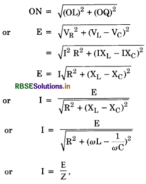
where Z = \(\sqrt{\mathrm{R}^2+\left(\omega \mathrm{L}-\frac{1}{\omega \mathrm{C}}\right)^2}\) is the effective opposition offered by L, C and R and is called the impedance of LCR-circuit.
Since Φ is the angle made by the resultant of (VR - VC) and R with x-axis, so from phasor diagram, we have:
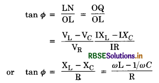
Now three cases are of interest:
(i) If ωL > 1/ωC i.e. the circuit is inductive dominant circuit and tan Φ is +ve, so the current will lag behind e.m.f. by a phase Φ.
(ii) If ωL < 1/ωC i.e. the circuit is capacitive dominant circuit and tan θ is -ve, so the current will lead the e.m.f. by a phase Φ.
(iii) If ωL = 1/ωC then tan Φ = 0 or Φ = 0 i.e. the current and e.m.f. will be in phase and the circuit is said to be in resonance.
Resonance frequency
Since tan Φ = \(\frac{\mathrm{X}_{\mathrm{L}}-\mathrm{X}_{\mathrm{C}}}{\mathrm{R}}\)
For resonance Φ = So XL - XC = 0
or XL = XC
or ωL = \(\frac{1}{\omega \mathrm{C}}\)
or ω2 = \(\frac{1}{\mathrm{LC}}\)
or resonance frequency
ωr = \(\frac{1}{\sqrt{\mathrm{LC}}}\)
Question 29.
Explain with the help of a labelled diagram, the principle and working of an a.c. generator? Write the expression for the emf generated in the coil in terms of speed of rotation. Can the current produced by an a.c. generator be measured with the help of moving coil galvanometer?
Answer:
Electric generator. A device which converts mechanical energy into electrical energy is called an electric generator or dynamo.
A.C. generator or A.C. dynamo
Principle. A.C. generator is based upon the phenomenon of electromagnetic induction i.e., whenever magnetic flux linked with a coil changes, an e.m.f. is induced in the coil.
Construction. It consists of the following essential parts:
1. Armature. It acts as a rotor. It consists of a large number of turns of insulated wires wound over a laminated soft iron core.

2. Magnet. Armature coil is rotated between pole pieces of a permanent (these days electromagnet) magnet.
3. Slip rings. AB is connected to the ring R1 and CD to ring R2. These rings rotate with the coil.
4. Brushes. B1 and B2 are two brushes or carbon rods. They are kept fixed and touch R1 and R2 lightly. The brushes are used to pass the current from armature coil to external load R.
Working. As armature coil rotates, the magnetic flux linked with the coil changes, hence induced e.m.f. is produced in the armature coil.
Let the armature ABCD is rotating in such a way that the arm AB moving upward and CD downward. By Flemings Right Hand Rule, we see that the induced current flows in the armature as shown in Fig. LAQ 25 (a).
By the time the armature turns through 180° (Fig. LAQ 25 b) with arm AB moving downward and CD moving upward, again applying Fleming’s Right Hand Rule, we find that the induced current flows in the armature as shown in Fig. LAQ 25 (b).
From Fig LAQ 25 (a) and LAQ 25 (b), we find that the directrion of induced e.m.f. and current in the external circuit is reversed after the armature has rotated through an angle 180°. Hence the current produced is alternating in nature
Theory. Let initially the coil is vertical i.e. θ = 0 at t = 0. Let at time t, if θ is angle through which it has rotated with angular velocity to ω (Fig. LAQ 25 (c, d))
So θ = ωt.
The magnetic flux linked with the coil.
Φ = n BA cos θ
or Φ = n BA cos ωt
Where n = number of turns of the coil
A = area enclosed‘by each turn of the coil
B = strength of magnetic field
θ = angle which the normal to the coil makes with \(\overrightarrow{\mathrm{B}}\) at any time t.
∴ Induced e.m.f.
E = -\(\frac{d \phi}{d t}=-\frac{d}{d t}\) (nBA cos ωt)
or E = -nBA \(\frac{d}{d t}\)(cos ωt)
E = nBA ω sin ωt. .............................(1)
E will be maximum if sin ωt = 1
If E0 is the maximum value of E, then
E0 = nBAω .........................(2)
Putting Eq.(2) in (1), we get
E = E0 sin ωt
or E = E0 sin θ ............................(3)
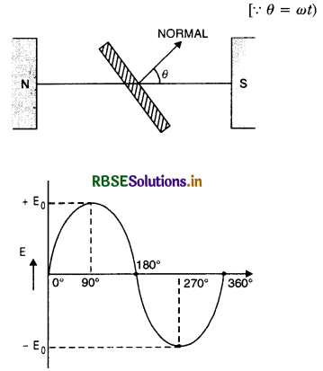
At θ = 0°, E = E0 sin 0 = 0
At θ = 90°, E = E0 sin 90 = E0
At θ = 180°, E = E0 sin 180° = 0
At θ = 270°, E = E0 sin 270° = -E0
At θ = 360°, E = E0 sin 360° = 0
If we plot a graph between θ and E, the graph is as shown in [Fig. LAQ 25 (d)]
Current produced by an a.c. generator cannot be measured by moving coil galvanometer, because the average value of ac over full cycle is zero.
Question 30.
Describe briefly, with the help of a labelled diagram the basic elements of an A.C. generator. State its underlying principle. Show diagrammatically how an alternating e.m.f. is generated by a loop of wire rotating in a magnetic field. Write the expression for the instantaneous value of the e.m.f. induced in the rotating loop.
Answer:
Electric generator. A device which converts mechanical energy into electrical energy is called an electric generator or dynamo.
A.C. generator or A.C. dynamo
Principle. A.C. generator is based upon the phenomenon of electromagnetic induction i.e., whenever magnetic flux linked with a coil changes, an e.m.f. is induced in the coil.
Construction. It consists of the following essential parts:
1. Armature. It acts as a rotor. It consists of a large number of turns of insulated wires wound over a laminated soft iron core.

2. Magnet. Armature coil is rotated between pole pieces of a permanent (these days electromagnet) magnet.
3. Slip rings. AB is connected to the ring R1 and CD to ring R2. These rings rotate with the coil.
4. Brushes. B1 and B2 are two brushes or carbon rods. They are kept fixed and touch R1 and R2 lightly. The brushes are used to pass the current from armature coil to external load R.
Working. As armature coil rotates, the magnetic flux linked with the coil changes, hence induced e.m.f. is produced in the armature coil.
Let the armature ABCD is rotating in such a way that the arm AB moving upward and CD downward. By Flemings Right Hand Rule, we see that the induced current flows in the armature as shown in Fig. LAQ 25 (a).
By the time the armature turns through 180° (Fig. LAQ 25 b) with arm AB moving downward and CD moving upward, again applying Fleming’s Right Hand Rule, we find that the induced current flows in the armature as shown in Fig. LAQ 25 (b).
From Fig LAQ 25 (a) and LAQ 25 (b), we find that the directrion of induced e.m.f. and current in the external circuit is reversed after the armature has rotated through an angle 180°. Hence the current produced is alternating in nature
Theory. Let initially the coil is vertical i.e. θ = 0 at t = 0. Let at time t, if θ is angle through which it has rotated with angular velocity to ω (Fig. LAQ 25 (c, d))
So θ = ωt.
The magnetic flux linked with the coil.
Φ = n BA cos θ
or Φ = n BA cos ωt
Where n = number of turns of the coil
A = area enclosed‘by each turn of the coil
B = strength of magnetic field
θ = angle which the normal to the coil makes with \(\overrightarrow{\mathrm{B}}\) at any time t.
∴ Induced e.m.f.
E = -\(\frac{d \phi}{d t}=-\frac{d}{d t}\) (nBA cos ωt)
or E = -nBA \(\frac{d}{d t}\)(cos ωt)
E = nBA ω sin ωt. .............................(1)
E will be maximum if sin ωt = 1
If E0 is the maximum value of E, then
E0 = nBAω .........................(2)
Putting Eq.(2) in (1), we get
E = E0 sin ωt
or E = E0 sin θ ............................(3)

At θ = 0°, E = E0 sin 0 = 0
At θ = 90°, E = E0 sin 90 = E0
At θ = 180°, E = E0 sin 180° = 0
At θ = 270°, E = E0 sin 270° = -E0
At θ = 360°, E = E0 sin 360° = 0
If we plot a graph between θ and E, the graph is as shown in [Fig. LAQ 25 (d)]
Question 31.
State the principle of an ac generator and explain its working with the help of a labelled diagram. Obtain the expression for the emf induced in a coil having N turns each of cross-sectional area A, rotating with a constant angular speed ‘ω’ in a magnetic field \(\overrightarrow{\mathbf{B}}\), directed perpendicular to the axis of rotation.
Answer:
Electric generator. A device which converts mechanical energy into electrical energy is called an electric generator or dynamo.
A.C. generator or A.C. dynamo
Principle. A.C. generator is based upon the phenomenon of electromagnetic induction i.e., whenever magnetic flux linked with a coil changes, an e.m.f. is induced in the coil.
Construction. It consists of the following essential parts:
1. Armature. It acts as a rotor. It consists of a large number of turns of insulated wires wound over a laminated soft iron core.

2. Magnet. Armature coil is rotated between pole pieces of a permanent (these days electromagnet) magnet.
3. Slip rings. AB is connected to the ring R1 and CD to ring R2. These rings rotate with the coil.
4. Brushes. B1 and B2 are two brushes or carbon rods. They are kept fixed and touch R1 and R2 lightly. The brushes are used to pass the current from armature coil to external load R.
Working. As armature coil rotates, the magnetic flux linked with the coil changes, hence induced e.m.f. is produced in the armature coil.
Let the armature ABCD is rotating in such a way that the arm AB moving upward and CD downward. By Flemings Right Hand Rule, we see that the induced current flows in the armature as shown in Fig. LAQ 25 (a).
By the time the armature turns through 180° (Fig. LAQ 25 b) with arm AB moving downward and CD moving upward, again applying Fleming’s Right Hand Rule, we find that the induced current flows in the armature as shown in Fig. LAQ 25 (b).
From Fig LAQ 25 (a) and LAQ 25 (b), we find that the directrion of induced e.m.f. and current in the external circuit is reversed after the armature has rotated through an angle 180°. Hence the current produced is alternating in nature
Theory. Let initially the coil is vertical i.e. θ = 0 at t = 0. Let at time t, if θ is angle through which it has rotated with angular velocity to ω (Fig. LAQ 25 (c, d))
So θ = ωt.
The magnetic flux linked with the coil.
Φ = n BA cos θ
or Φ = n BA cos ωt
Where n = number of turns of the coil
A = area enclosed‘by each turn of the coil
B = strength of magnetic field
θ = angle which the normal to the coil makes with \(\overrightarrow{\mathrm{B}}\) at any time t.
∴ Induced e.m.f.
E = -\(\frac{d \phi}{d t}=-\frac{d}{d t}\) (nBA cos ωt)
or E = -nBA \(\frac{d}{d t}\)(cos ωt)
E = nBA ω sin ωt. .............................(1)
E will be maximum if sin ωt = 1
If E0 is the maximum value of E, then
E0 = nBAω .........................(2)
Putting Eq.(2) in (1), we get
E = E0 sin ωt
or E = E0 sin θ ............................(3)

At θ = 0°, E = E0 sin 0 = 0
At θ = 90°, E = E0 sin 90 = E0
At θ = 180°, E = E0 sin 180° = 0
At θ = 270°, E = E0 sin 270° = -E0
At θ = 360°, E = E0 sin 360° = 0
If we plot a graph between θ and E, the graph is as shown in [Fig. LAQ 25 (d)]
Question 32.
When an inductor L and a resistor R in series are connected across a 12V, 50 Hz supply of current of 0.5A flows in a circuit. The current differs in phase from applied voltage to \(\frac{\pi}{3}\) radius calculate the value of R.
Answer:
Z = \(\frac{\mathrm{E}}{\mathrm{I}}=\frac{12}{0.5}\) = 2 - 2
cos Φ = \(\frac{\mathrm{R}}{2}\) So,
R = Z cos Φ = 24 x cos 60° = 27 x \(\frac{1}{2}\) = 12 Ω
Question 33.
In a series LCR circuit across an a.c. source of variable frequency, obtain the expression for its impedance and draw a plot showing its variation with frequency of the a.c. source.
Answer:
Impedance of LCR circuit
Let an inductance L, capacitance C and resistance R be connected in series to an alternating source of e.m.f. E as shown in Fig.LAQ 12(a).

The alternating current at all points in a series circuit has the same amplitude and phase, but the voltage across each element will be of different amplitude and phase.
(i) If VR is the voltage across R, then
VR = IR
The voltage across the resistor in the phase with current.
(ii) If VL is the voltage across L, then
VL = I XL
The voltage across the inductor leads the current by a phase π/2.
(iii) If VC is the voltage across C, then
VC = IXC
The voltage across the inductor lags behind the current by a phase π/2.
Let us construct the phasor diagram for this circuit. A single phasor I is used to represent the current in each element and VR, VL and VC represent voltage phasors.
If VR is represented along OX by OL (current along OX), VL and VC will be perpendicular to x-axis. Let VL acts along Y-axis and represented by OM and VC acts along Y'-axis and represented by OP. So VL and VC all acting along the same line but in opposite directions. If VL > VC, then (VL - VC) is along VL represented by OQ and perpendicular to phasor VR as shown in Fig. LAQ 12 (b). The sum of VR, VL and VC equal to E and makes an angle Φ with the current I
From the phasor diagram, we find that

where Z = \(\sqrt{\mathrm{R}^2+\left(\omega \mathrm{L}-\frac{1}{\omega \mathrm{C}}\right)^2}\) is the effective opposition offered by L, C and R and is called the impedance of LCR-circuit.
Since Φ is the angle made by the resultant of (VR - VC) and R with x-axis, so from phasor diagram, we have:

Now three cases are of interest:
(i) If ωL > 1/ωC i.e. the circuit is inductive dominant circuit and tan Φ is +ve, so the current will lag behind e.m.f. by a phase Φ.
(ii) If ωL < 1/ωC i.e. the circuit is capacitive dominant circuit and tan θ is -ve, so the current will lead the e.m.f. by a phase Φ.
(iii) If ωL = 1/ωC then tan Φ = 0 or Φ = 0 i.e. the current and e.m.f. will be in phase and the circuit is said to be in resonance.
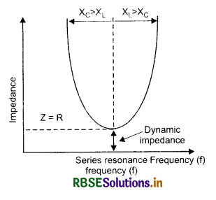
Question 34.
How much current is drawn by the primary coil of a transformer which steps down 220 V to 22 V to operate a device with an impedance of 220?
Answer:
Is = \(\frac{\mathrm{V}_{\mathrm{s}}}{\mathrm{Z}}=\frac{22}{220}\)0.1 A
since VpIp = VsIs
∴ Ip = \(\frac{\mathrm{V}_{\mathrm{s}} \mathrm{I}_s}{\mathrm{~V}_p}=\frac{22 \times 0.1}{220}\) = 0.01 A
Question 35.
An aeroplane is flying horizontally from west to east with a velocity of 900 km/hour. Calculate the potential difference developed between the ends of its wings having a span of 20 m. The horizontal component of the Earth’s magnetic field is 5 x 10⁻⁴ T and the angle of dip is 30°.
Answer:
Here B = 5 x 10⁻⁴ T, θ = 30°, l = 20m
v = 900 km h-1 = 900 x \(\frac{10}{18}\)
= 250 ms-1
When aeroplane is flying horizontally from west to east its wings cross vertical component of earth’s magnetic field
∴ B1 = B sin θ = 5 x 10⁻⁴ x sin 30°
= 2.5 x 10⁻⁴ T
The potential difference developed between the ends of its wings
ε = B l v
= 2.5 x 10-4 x 20 x 250
= 1.25 volt.
HOTS QUESTIONS
Question 1.
In a series LCR circuit the voltage across an inductor, capacitor and resistor are 20V, 20V and 40V respectively. What is the phase difference between the applied voltage and the current in the circuit?
Answer:
Since VL = VC, so the LCR circuit is in resonance. Hence the applied voltage and current are in the same phase.
Question 2.
When a capacitor is connected in series LR circuit the alternating current flowing in the circuit inceases. Explain why.
Answer:
In LR circuit, the impedance is given by
ZL = \(\sqrt{\mathrm{R}^2+\mathrm{X}_{\mathrm{L}}^2}\) ..........................(i)
In LCR circuit, the impedance is given by
Z = \(\sqrt{\mathrm{R}^2+\left(\mathrm{X}_{\mathrm{L}}-\mathrm{X}_{\mathrm{C}}\right)^2}\) .............................(ii)
From eqns. (i) and (ii), we find that
Z < ZL
Since I = \(\frac{E}{Z}\)
As Z decreases on connecting a capacitor in series with LR circuit, hence the current I in the circuit increases.
Question 3.
A 12V resistance and an inductance of \(\frac{0.05}{\pi}\)H are connected in series. Across the end of this circuit an alternating voltage of 130 V and frequency 50Hz is connected. Calculate the current in the circuit and the potential difference across the inductance.
Answer:
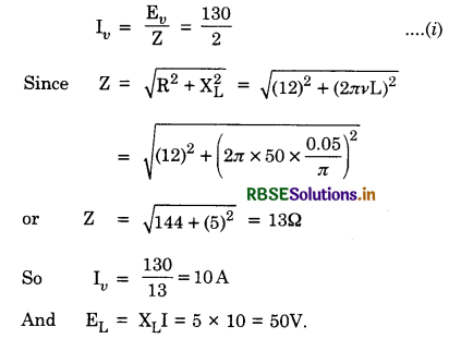
Question 4.
In the given circuit, calculate (i) current in the circuit (ii) potential difference across each element.
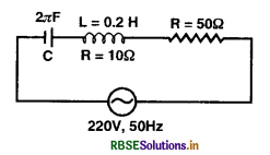
Answer:
Total resistance in the circuit
R1 = R + 10 = 50 + 10 = 60 Ω
XL = 2πvL = 2 x 3.14 x 50 x 0.2 = 62.8 Ω
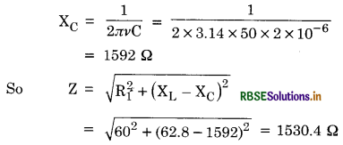
(i) Current in the circuit
Iv = \(\frac{\mathrm{E}_v}{\mathrm{Z}}=\frac{220}{1530.4}\) = 0.14 A
Potential diff. across R = IvR = 0.14 x 50 = 7V
Potential diff. across L
= Iv \(\sqrt{r^2+X_L^2}\)
= 0.41 \(\sqrt{10^2+(62.8)^2} \)= 8.9 V
(ii) Potential diff. across C = IvXC = 0.14 x 1592 = 222.9V
Question 5.
The given circuit diagram shows a series LCR circuit connected to a variable frequency 230 V source.
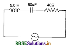
(a) Determine the source frequency which drives the circuit in resonance.
(b) Obtain the impedence of the circuit and the amplitude of current at resonating frequecny.
(c) Determine the RMS potential drops across the three elements of the circuit.
(d) How do you explain the observation that the algebraic sum of the voltages across the three elements obtained in (c) is greater than the supplied voltages?
Answer:
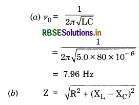
At resonance XL = XC
∴ Z = R = 40 Ω
And Iv = \(\frac{\mathrm{E}_v}{\mathrm{R}}=\frac{230}{40}\)
Amplitude of current
I0 = \(\sqrt{2}\)Iv = 1.414 x 5.75 = 8.13 A
(c) Potential drop across, R = IvR = 5.75 x 5 = 28.75 Ω
Potential drop across L = Iv x 2πv0L
= 5.75 x 2π x 7.96 x 5.0
= 1437.5 V
Potential drop across L = 1437.5 [∵ XL = XC at resonance]
(d) Though algebric sum may be greater than the supply but the vector sum remains the same. This is due to the phase difference between these voltage components.

- RBSE Class 12 Physics Notes Chapter 2 स्थिर वैद्युत विभव तथा धारिता
- RBSE Class 12 Physics Notes Chapter 3 विद्युत धारा
- RBSE Class 12 Physics Notes Chapter 4 गतिमान आवेश और चुंबकत्व
- RBSE Class 12 Physics Notes Chapter 5 चुंबकत्व एवं द्रव्य
- RBSE Class 12 Physics Notes Chapter 6 वैद्युत चुंबकीय प्रेरण
- RBSE Class 12 Physics Notes Chapter 7 प्रत्यावर्ती धारा
- RBSE Class 12 Physics Notes Chapter 8 वैद्युतचुंबकीय तरंगें
- RBSE Class 12 Physics Notes Chapter 9 किरण प्रकाशिकी एवं प्रकाशिक यंत्र
- RBSE Class 12 Physics Notes Chapter 10 तरंग-प्रकाशिकी
- RBSE Class 12 Physics Notes Chapter 11 विकिरण तथा द्रव्य की द्वैत प्रकृति
- RBSE Class 12 Physics Notes Chapter 12 परमाणु