RBSE Class 12 Physics Important Questions Chapter 6 Electromagnetic Induction
Rajasthan Board RBSE Class 12 Physics Important Questions Chapter 6 Electromagnetic Induction Important Questions and Answers.
RBSE Class 12 Physics Chapter 6 Important Questions Electromagnetic Induction
Multiple Choite Questions
Question 1.
SI unit of magnetic flux is:
(A) gauss
(B) weber
(C) oersted
(D) tesla.
Answer:
(B) weber

Question 2.
In electromagnetic induction, the induced e.m.f. in a coil is independent of:
(A) charge of flux
(B) time
(C) number of turns of coil
(D) resistance of the coil.
Answer:
(D) resistance of the coil.
Question 3.
Lenz’s law is a consequence of the law of conservation of:
(A) charge
(B) momentum
(C) energy
(D) mass.
Answer:
(C) energy
Question 4.
A two metre wire is moving with a velocity of 1 m/s perpendicular to a magnetic field of 0.5 Wb/m2. The e.m.f. induced in it will be:
(A) 0.5 V
(B) 0.1 V
(C) 1 V
(D) 2 V.
Answer:
(C) 1 V

Question 5.
What is the unit of self-inductance of a coil?
(A) Volts-1 A
(B) Volts-1 A-1
(C) Volt sec Ampere
(D) Volt sec A-1.
Answer:
(D) Volt sec A-1.
Question 6.
A 100 mH coil carries a current of 1 ampere energy stored in it is:
(A) 0.5 J
(B) 1 J
(C) 0.05 J
(D) 0.1 J.
Answer:
(C) 0.05 J
Question 7.
Which of the following is not an application of eddy currents?
(A) Inductance furnace
(B) Crystallography
(C) Galvanometer damping
(D) Speedometer of automobile.
Answer:
(B) Crystallography
Question 8.
Eddy current does not cause:
(A) Damping
(B) Heating
(C) Sparking
(D) Loss of energy.
Answer:
(C) Sparking
Question 9.
Eddy currents are produced in:
(A) induction furnace
(B) electromagnetic brakes
(C) speedometer
(D) all of these.
Answer:
(D) all of these.
Question 10.
What is basic cause of induced e.m.f.?
(A) Change in electric flux linking with a coil
(B) Change in magnetic flux linking with a coil
(C) (A) and (B)
(D) None.
Answer:
(B) Change in magnetic flux linking with a coil

Question 11.
State Lenz’s law:
(A) Same as coulomb’s law
(B) Same as Ohm’s law
(C) Same as Kirchhoff s law
(D) None of these.
Answer:
(D) None of these.
Question 12.
The number of turns of a coil is doubled. How will its self-inductance be effected?
(A) remains same
(B) doubles
(C) become four times
(D) becomes half.
Answer:
(C) become four times
Question 13.
Dynamo works on the principle of:
(A) electromagnetic induction
(B) heating effect of current
(C) Chemical effect of current
(D) None of these.
Answer:
(A) electromagnetic induction
Question 14.
The unit of inductance is:
(A) volt/ampere
(B) volt x sec/ampere
(C) joule/ampere
(D) volt x ampere.
Answer:
(B) volt x sec/ampere
Question 15.
Whenever changing current is passed through a conductor, an e.m.f. is induced, that is:
(A) Newton’s law
(B) Ohm’s law
(C) Kirchhoffs law
(D) Faraday’s law.
Answer:
(D) Faraday’s law.
Question 16.
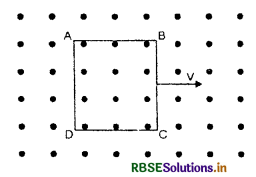
A metallic square loop ABCD is moving in its own plane with velocity V in a uniform magnetic field perpendicular to its plane as shown in the Fig. An electric field is induced.
(A) in AD, but not in BC
(B) in BC, but not in AD
(C) neither in AD nor in BC
(D) in both AD and BC.
Answer:
(C) neither in AD nor in BC
Question 17.
A straight conductor of length 4 metres move at a speed of 10 m/sec when the conductor makes an angle of 30° with the direction of magnetic field of induction 0.1 weber per metre2. Then the induced e.m.f. is:
(A) 1 volt
(B) 2 volt
(C) 4 volt
(D) 8 volt.
Answer:
(B) 2 volt
Question 18.
A copper ring having a cut such as not to form a complete loop is held horizontally and a bar magnet is dropped through the ring with its length along the axis of the ring. Then acceleration of the falling magnet is:
(A) g
(B) less than g
(C) more than g
(D) 0
Answer:
(A) g

Question 19.
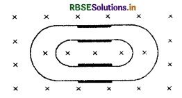
One conducting U tube can slide inside another as shown in figure maintaining electric contracts between the tubes. The magnetic field B is ⊥ to the plane of the figure. If each tube move towards the other at a constant speed V, then the e.m.f. induced in the circuit in terms of B, l and V, where l is the width of each tube, will be:
(A) zero
(B) 2BlV
(C) BlV
(D) - BlV
Answer:
(A) zero
Question 20.
Two different loops are concentric and lie in the same plane. The current in the outer loop is clockwise and increasing with time. The induced current in the inner loop then, is:
(A) clockwise
(B) zero
(C) counter-clockwise
(D) in a direction that depends on the ratio of the loop radii.
Answer:
(C) counter-clockwise
Question 21.
The current through a solenoid increases at a constant rate, then the induced current:
(A) is constant and is in the direction of the induced current
(B) is constant and is in the direction opposite to that of the inducing current
(C) increases with time and is in the direction of the inducing current
(D) increases with time and opposite to the direction of the inducing current.
Answer:
(D) increases with time and opposite to the direction of the inducing current.
Fill in the blanks
Question 1.
Total number of magnetic lines passing through a surface is called ................................ .
Answer:
magnetic flux.
Question 2.
The product of area and component of magnetic field normal to area is called ................................ .
Answer:
magnetic flux.

Question 3.
................................ law obeys law of conservation of energy.
Answer:
Lenz’s.
Question 4.
Dimensional formula of B is ................................ .
Answer:
[M1 L0 T-2 A-1].
Question 5.
Dimensional formula of magnetic flux is ................................ .
Answer:
[M1 L2 T-2 A-1].
Question 6.
Non induction coils are used in the ................................ boxes.
Answer:
resistance.
Question 7.
The direction of induced e.m.f. is such that it always ................................ the cause which ................................ it.
Answer:
opposes, produces.

Question 8.
Electromagnetic damping is the application of ................................ currents.
Answer:
eddy.
Question 9.
Eddy current can be reduced by using ................................ cores.
Answer:
laminated.

Question 10.
SI unit of self/mutual inductance is ................................ .
Answer:
henry.
Very Short Answer Type Questions
Question 1.
Name the unit of magnetic flux.
Answer:
weber.
Question 2.
Name the unit of magnetic induction.
Answer:
tesla.
Question 3.
Name the methods of producing induced emf.
Answer:
- By change of magnetic field
- By change of orientation of coil
- By change of area.

Question 4.
Induced emf is called back emf, why?
Answer:
Because it opposes growth of current.
Question 5.
Does Lenz’s law violate the principle of energy conservation?
Answer:
No. It simply converts mechanical energy into electrical energy.
Question 6.
When is the magnetic flux with a coil held in a magnetic field zero?
Answer:
When the plane of coil is along the field.
Question 7.
Why is spark produced in the switch of a fan when it is put off?
Answer:
Due to self-induction, the spark is produced when the current in the circuit (and hence magnetic flux) changes from the maximum to zero.
Question 8.
State Lenz’s law.
Answer:
It states that the direction of induced e.m.f. is such that it always opposes the cause which produces it.
Question 9.
Weber is the unit of which physical quantity?
Answer:
Magnetic flux.
Question 10.
A magnet is moved towards a coil. What is the source of electric current induced in the coil?
Answer:
Mechanical energy used to move the magnet towards the coil is converted into electrical energy and induced current is produced in the coil.

Question 11.
A coil and a bar magnet move with the same velocity. What will be induced e.m.f. in the coil?
Answer:
No induced e.m.f. will be produced in the coil.
Question 12.
If a magnet is held stationary and a coil is moved towards the magnet, will there be any induced e.m.f. produced in the coil?
Answer:
Yes. Because induced e.m.f. is produced due to relative motion between the coil and the magnet.
Question 13.
A wire in N-S direction is pin dropped freely. Will any potential difference be induced across its ends?
Answer:
No, because there is no change in the horizontal component and vertical component of earth’s magnetic field due to the fall of the wire.
Question 14.
If the wire kept in E-W direction be dropped freely, then, is there any potential difference induced across its ends?
Answer:
Yes, because the horizontal component of earth’s magnetic field is intercepted by the wire and hence potential difference is induced across the ends of the falling wire.
Question 15.
What is the relationship between e.m.f. and magnetic flux?
Answer:
If e is induced e.m.f. and Φ is magnetic flux, then e = -\(\frac{d \phi}{d t}\).

Question 16.
A solenoid with an iron core and a bulb are connected to a d.c. source. How does the brightness of the bulb change, when the iron core is removed from the solenoid?
Answer:
On removing the iron core from the solenoid, the magnetic flux linked with the coil decreases and induced e.m.f. is produced, hence the brightness of the bulb will increase.
Question 17.
How does the self-inductance of a coil change when an iron rod is introduced in the coil?
Answer:
The self inductance of the coil will increase because L ∝ µr.
Question 18.
Could a current be induced in a coil by rotating a magnet inside the coil? If so, how?
Answer:
Yes, by holding a magnet along the axis of the coil and turning the magnet about the diameter of the coil.
Question 19.
Name the physical quantity whose S.I. unit is weber, is it a scalar or a vector quantity?
Answer:
Magnetic flux has the unit as Weber and it is a scalar quantity.
Question 20.
Metallic wire lm in length is moving normally across a field of 0.1 T with a speed of 5 ms-1. Find the e.m.f. between the ends of the wire.
Answer:
Induced e.m.f. e = Blv = 0.1 x 1 x 5 = 0.5 V

Question 21.
What is the principle of electromagnetic damping?
Answer:
When a conductor is made to rotate in a magnetic field, the magnetic flux linked with the conductor changes and induced e.m.f. and hence induced current is produced. The direction of induced current is such that it always opposes the cause of its production in accordance with Lenz’s law, hence it opposes the rotation of conductor and stops its motion. This is called electromagnetic damping.
Question 22.
Magnetic flux is misnomer. Explain.
Answer:
The term flux is generally used when something is flowing out of certain material, for example, water coming out of tap called flux of water. But in case of magnetic flux, there is nothing that really flows through the surface. Hence it is misnomer.
Question 23.
Why self induction is called inertia of electricity?
Answer:
Because self induction opposes the variation in current in an electric circuit which is analogous to inertia of a body which opposes any change in its position.
Question 24.
What is self inductance?
Answer:
The phenomenon according to which an induced e.m.f. or current is produced in a coil, when changing current is passed through it is called self-inductance.
Question 25.
What is meant by mutual induction?
Answer:
Mutual induction is the property of two neighbouring coils by virtue of which each opposes any change in the strength of current flowing through the other by developing an induced e.m.f.
Question 26.
What factors govern the direction of e.m.f.?
Answer:
The direction of induced e.m.f. always opposes the causes which produces it.
Question 27.
What causes eddy currents?
Answer:
The change in magnetic flux linked with a conductor is the cause of eddy currents.
Question 28.
Two inductors L1 and L2 sufficient distance apart are connected (i) in series (ii) in parallel. What is their equivalent inductance?
Answer:
In series combination
Ls = L1 + L2
In parallel combination
Lp = \(\frac{\mathrm{L}_1 \mathrm{~L}_2}{\mathrm{~L}_1+\mathrm{L}_2}\)
Question 29.
Will an induced current be always produced whenever there is change of magnetic flux linked with a coil?
Or
Does change in magnetic flux induce emf or current?
Answer:
The induced current is produced only if the circuit is closed but the induced e.m.f. will be definately produced.
Question 30.
If the rate of change of current. 2As-1 induces an e.m.f. of 40 mV in a solenoid, what is the self inductance of this solenoid?
Answer:
Since
L = \(-\frac{e}{\frac{d \phi}{d t}}\)
∴ L = \(-\frac{40 \times 10^{-23}}{2}\)
= -20 x 10-3 H
In magnitude
L = 20 x 10-3 H
Question 31.
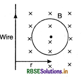
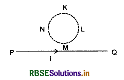
What is the magnitude of the induced currents in circular loop KLMN of radius r if the straight wire PQ carries a steady current of magnitude i ampere.
Answer:
The magnitude of induced current is zero, because there is no change in the magnetic flux linked with the loop.
Question 32.
Define 1 henry.
Answer:
One henry is the self inductance of that coil in which 1V emf is produced when the rate of change of current in that coil is 1 As-1.

Question 33.
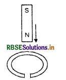
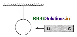
Give the direction in which induced current flows in the wire loop, when the magnet moves towards the loop as shown.
Answer:
When N-pole of the magnet moves towards the coil, the near face of the coil acquire N-pole, hence the direction of induced current is anticlockwise.
Question 34.
If the number of turns of a solenoid is doubled keeping the other factors constant, how does the self-inductance of solenoid change?
Answer:
Since the self-inductance is directly proportional to the number of turns in the coil, hence it will be doubled.
Question 35.
If the self-inductance of an iron ore inductor increases from 0.01 m H to 10 mH on introducing the iron core into it, what is the relative permeability of the core used?
Answer:
Relative permeability
µr = \(\frac{10 m \mathrm{H}}{0.01 m \mathrm{H}}\) = 1000.
Question 36.
Name the physical quantity whose S.I. unit is weber. Is it a scalar or a vector quantity?
Answer:
Magnetic flux has the unit as weber and it is a scalar quantity.
Question 37.
A solenoid with an iron core and a bulb are connected to a d.c. source. How does the brightness of the bulb change, when the iron core is removed from the solenoid?
Answer:
On removing the iron core from the solenoid, the magnetic flux linked with the coil decreases and induced e.m.f. is produced, hence the brightness of the bulb will increase.
Question 38.
What is the basic cause of induced e.m.f.?
Answer:
The basic cause of induced e.m.f. is the rate of change of magnetic flux linked wdth a coil or a closed circuit.

Question 39.
Two identical loops, one of copper and another of constantan are removed from a magnetic field within the same time interval. In which loop will the induced current be greater?
Answer:
The induced e.m.f. will be the same but the induced current will be more in copper loop as its resistance will be lesser as compared to that of the constantan loop.
Question 40.
State Lenz’s law of electromagnetic induction.
Answer:
It states that the direction of induced e.m.f. (or current) produced in a circuit is such that it always opposes the cause producing it.
Question 41.
Predict the polarity of the capacitor in the situation described below.

Answer:
Since the induced emf always opposes the cause which produces it (Lenz law). So the polarity of the capacitor is as shown in Fig. VSAQ 41 (b).

Question 42.
A bar magnet falls from a height h through a metallic ring. Will its acceleration be equal to g? Give reason for your answer.
Answer:
The acceleration of the magnet will be less than g. Because when the magnet falls, the magnetic flux linked with the coil increases and induced e.m.f. is produced which opposes the acceleration of the magnet in accordance to Lenz's law.
Question 43.
Define mutual inductance and give its S.I. unit.
Answer:
Mutual inductance of two coils is numerically equal to the amount of magnetic flux linked wi th one coil when unit current flows through the neighbouring coil.
The unit of mutual inductance is henry.
Question 44.
What are S.I. units of (i) magnetic flux (ii) magnetic field strength and (iii) self inductance.
Answer:
(i) Weber
(ii) tesla
(iii) henry.

Question 45.
Why does acceleration of a magnet falling through a long solenoid decrease?
Answer:
Because the induced current in the solenoid offers retarding force of the falling magnet and thus reduces its acceleration.
Short Answer Type Questions
Question 1.
A coil is placed in a magnetic field. What should be its orientation with the field for the flux to be (i) maximum (ii) minimum? When is it taken to be positive and when as negative?
Answer:
- The magnetic flux linked with the coil will be maximum, wrhen the plane of the coil is normal to the magnetic field.
- The magnetic flux linked with the coil will be minimum, when the plane of the coil is parallel to the magnetic flux.
The magnetic flux is taken to be positive, if the normal to the plane is in the direction of magnetic field and negative if the normal to the plane is opposite to the direction of magnetic field.
Question 2.
State Faraday’s laws of electromagnetic induction.
Answer:
First law. Whenever the amount of magnetic flux linked with a circuit changes, an e.m.f. is induced in the circuit. The induced e.m.f. lasts so long as the change in the magnetic flux continues.
Second law. The magnitude of e.m.f. induced in the circuit is directly proportional to the rate of change of magnetic flux linked with the circuit.
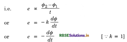
-ve sign means opposing nature of induced e.m.f.
Question 3.
State and explain Faraday’s laws of electromagnetic induction.
Answer:
First law. Whenever the amount of magnetic flux linked with a circuit changes, an e.m.f. is induced in the circuit. The induced e.m.f. lasts so long as the change of magnetic flux continues.
Explanation. When a magnet is moved towards or away from a coil, the number of magnetic lines linked with coil increases and vice versa. In both the cases, galvanometer put in the circuit shows deflection. When there is no relative motion between magnet and coil, no deflection in galvanometer is observed since magnetic field in this case is constant.
Second law. The magnitude of e.m.f. induced in a circuit is directly proportional to the rate of change of magnetic flux linked with the circuit.
Explanation. In Faraday’s experiment, if we move the magnet faster, more deflection will be obtained in galvanometer. Again, more deflection will be obtained if we move a stronger magnet. This shows that e.m.f. induced is proportional to the rate of change of magnetic flux.
Question 4.
A circular brass loop of radius a and resistance R is placed with its plane perpendicular to the magnetic field which varies with time as B = B0 sin ωt. Obtain an expression for the induced current in the loop.
Answer:
(i) Φ = \( \overrightarrow{\mathrm{B}} \cdot \overrightarrow{\mathrm{A}}\) = BA cos 0°
or Φ = B0 sin ωt x πa2
(ii) e = \(-\frac{d \phi}{d t}=-\frac{d}{d t}\)(B0 sin ωt) x πa2
∴ e = -πa2 B0 ω cos ωt
(iii) I = \(\frac{e}{\mathrm{R}}=\frac{-\pi a^2 \mathrm{~B}_0 \omega \cos \omega t}{\mathrm{R}}\)

Question 5.
Explain on what factors does the induced e.m.f. in a coil rotating in uniform magnetic field depend.
Answer:
The induced e.m.f. in a coil rotating in a magnetic field depends on:
- area of the coil, A
- number of turns in the coil, N
- angular velocity of the coil, ω
- strength of uniform magnetic field, B
e = NBA ω
Question 6.
An artificial satellite with a metal surface has an orbit over the equator. Will the earth’s magnetism induce a current in it?
Answer:
No, because in the equatorial orbit, the satellite cuts the same number of magnetic lines of force at all times, so there is no change of flux.
Question 7.
How would you detect the presence of magnetic field on an unknown point?
Answer:
Two ends of a coil are connected to a sensitive galvanometer and the coil is rotated. If the galvanometer shows the deflection, the magnetic field is there, otherwise not.
Question 8.
Why is induced e.m.f. also called motional e.m.f.?
Answer:
When a conductor is moved in a magnetic field, the free electrons in it are forced from one end to other end, hence a potential difference i.e. induced e.m.f. is produced at the end of the conductor. Since this induced e.m.f is produced due to motion of the conductor so it is also called motional e.m.f.
Question 9.
Show that the Lenz’s law is a direct consequence of the law of conservation of energy.
Or
What is Lenz’s law? Show that it is in accordance with the law of conservation of energy.
Answer:
Lenz’s law. It states that the direction of induced e.m.f. is such that it always opposes the cause which produces it.
Lenz’s law obeys law of conservation of energy.
When N pole (or S pole) of a magnet is moved towards a coil, the induced current is produced in the coil and it makes the front face of the coil a north pole (or south pole). Thus a force of repulsion between the magnet and the coil takes place. To overcome this force of repulsion, some work has to be done against the force of repulsion. This mechanical work done is converted into electric energy. Hence Lenz's law is in accordance with law of conservation of energy.

Question 10.
A small resistor, say a lamp is usually put in parallel to the current carrying coil in an electromagnet. Why?
Answer:
When the current in the coil is switched on, a large induced e.m.f. is produced which causes spark. A small resistor in parallel provides a conducting path, hence the spark and other risks of high voltage are avoided.
Question 11.
Deduce an expression for the self inductance of a long solenoid of N turns, having a core of relative permeability µr.
Answer:
Expression for Coefficient of self-induction for a Solenoid
Consider a solenoid of length l
Let r = radius of solenoid such that r < l
n = no. of turns per unit length
I = strength of current through the solenoid
The magnetic field produced by the current inside the solenoid is practical constant and B = µ0 nI
∴ Magnetic flux linked with the loop, dΦ = µ0n IA
Magnetic flux linked with entire solenoid Φ = nl (µ0 n IA) = µ0n2lAI
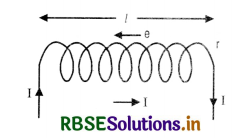
Since Φ = LI
∴ LI = µ0n2 l I A
L = µ0n2 l A .............................(i)
If the coil is wound on a material having relative permittivity µr then L = µ0 µr n2 l A
Question 12.
In the figure SAQ 12 (a) a bar magnet moving towards the right or left induces an e.m.f. in the coils (1) and (2). Find, giving reason, the direction of induced currents through resistors AB and CD. When the magnet is moving (a) towards the right and (b) towards the left.

Answer:
(a) When the magnet is moving towards right. When the magnet is moving towards right, the N pole of the magnet is moving away from coil (1) and is approaching towards coil (2), hence it forms S-pole in coil (1) (due to clockwise current) and the current is from A to B Fig. SAQ 12 (b) and S pole is also formed in coil (2). (due to induced clockwise current) and the current is from D to C.

(b) When the magnet is moving towards left. Here N-pole is approaching towards coil (1) and S-pole is receding away from coil (2), So N-pole is formed both in coil (1) and (2) as shown in Fig. 12 (c).

Question 13.
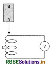
The figure SAQ 13 (a) shows a bar magnet M falling under gravity through an air cored coil. Plot a graph showing variation of induced e.m.f. with time (t). What does the area enclosed by E-t curve depict?
Answer:
The graph between E and t is as shown in Fig. SAQ 13 (b). Here as the magnet approaches the coil, E will go on increasing up to b. When the magnet fully enters the coil given by point c, there is no change in magnetic flux, it is shown by c in Fig. SAQ 13 (b).
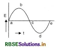
And again when it is coming out from the coil, the value of E increases in reverse direction.
Area below E-t graph gives the magnetic flux because
Et = flux [∵ \(\frac{d \phi}{d t}\) = E or dΦ = E dt]
Question 14.
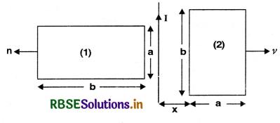
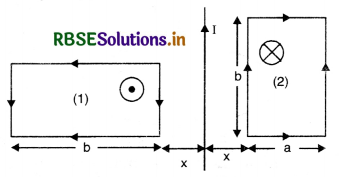
The figure SAQ 14 (a) shows two identical rectangular loops (1) and (2) placed along with a straight long current carrying conductor between them.
(i) What will be the direction of induced currents in the loops when they are pulled away from the conductor with the same velocity v?
(ii) Will the e.m.f. induced in the two loops be equal?
Answer:
According to Fleming’s right hand rule, the magnetic field due to current I on loop (1) is vertically downward and perpendicular to the plane of paper and hence the current will be clockwise (Fig. SAQ 14 (b) and in loop (2), the magnetic field is directed outwards and perpendicular to the plane of paper and the current will be in anticlockwise direction as shown in Fig. SAQ 14 (b).
Question 15.
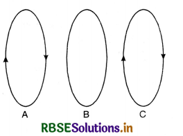
The identical coils A, B and C are placed with their planes parallel to one another. Coil A and coil C carry the electric current as shown in Fig. SAQ 15 coil B and C are fixed. Coil A is moved towards B with a constant speed. Is their any induced current in B?
Answer:
Since the coil B and C are fixed, so induced current will be produced in loop B due to C. But as A is moved towards B, an induced e.m.f. will be produced in B and the direction of induced current in B is such that it opposes the motion of A as predicted by Lenz’s law.
i.e. the direction of induced current in B will be in the direction of current in C.

Question 16.
Explain the production of eddy currents in a conductor.
Answer:
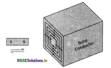
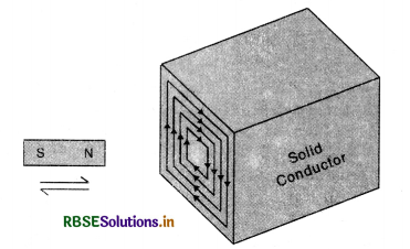
Eddy current. When a solid conductor moves across a magnetic field or is placed in a changing magnetic field, the flux linked with the conductor changes and, therefore, induced (circulating) currents are set up in the conductor. In accordance with Lenz’s law, the direction of the induced currents opposes the motion of the conductor or the charges in the field to which they are due. Such circulating currents are called Focault's currents or eddy currents. Since the resistance of metal piece is quite low, these currents may be quite large and may produce heating or damping effects. Fig. LAQ 8 (a).
Thus eddy currents are the current induced in a conductor, when placed in changing magnetic field.
Magnitude of eddy current
I = \(\frac{\text { Induced e.m.f }(e)}{\text { Resitance }(\mathrm{R})}=\frac{e}{\mathrm{R}}\)
Since e = \(-\frac{d \phi}{d t}\)
∴ I = \(-\frac{d \phi / d t}{\mathrm{R}}=-\frac{1}{\mathrm{R}} \frac{d \phi}{d t}\)
The direction of I is given by Lenz’s law or Fleming’s right hand rule.
Note. Fleming’s Right Hand Rule
It states that if we stretch the first finger, central finger and thumb of our right hand in mutually perpendicular directions such that the first finger points along the direction of magnetic field and the thumb along the direction of motion of the conductor, tfien central finger would gives us the direction of induced e.m.f.
Illustrations
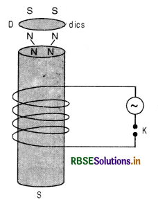
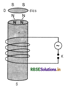
(i) If a light metallic disc D is placed at top of an electromagnet as shown in Fig. LAQ 8 (b) and a.c. is passed through the coil, the disc is thrown up due to eddy currents.
Explanation. On passing the current in the coil, the magnetic flux linked with the coil starts growing and thus magnetic flux linked with the solenoid and hence with the disc also increases and induced current is produced in the disc which converts it into a small magnet. The upper end of the iron core and lower face of the disc acquire the same polarity in accordance with Lenz’s law and due to repulsion between the upper end of soft iron and lower face of disc D, the disc is thrown up.
(ii) A simple pendulum is made of sheet of copper as shown in Fig. LAQ 8 (c). It is made to oscillate between the pole piece of an electromagnet. When the magnetic field is off, the metal plate oscillates freely for a long time. But when the magnetic field is switched on, the motion of the plate is damped due to production of eddy currents, because when the metal plate is displaced towards any one extreme position the area of the plate in the field decreases and magnetic flux linked with the plate decreases and eddy currents are produced which opposes the motion of the plate and thus produces damping. If the strength of magnetic field is very high, the plate is unable to move in the magnetic field and its motion becomes dead beat.
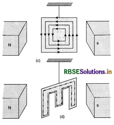
If the same experiment is repeated by a slotted plate Fig. LAQ 8 (d) the motion of plate is not much affected by the magnetic field because eddy currents are reduced as the same closed loop has a much longer path as shown by dotted closed line in Fig.(d). Longer path means more resistance, hence eddy currents will be reduced.
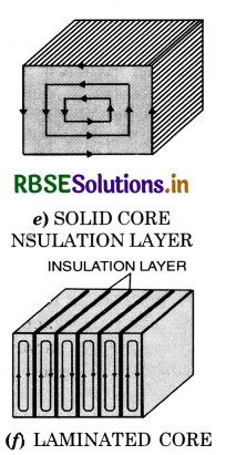
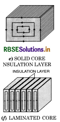
In a transformer the changing magnetic flux produces eddy currents in the iron core of the transformer and leads to the wastage of energy in the form of heat. This wastage of energy can be minimised by using a laminated iron core.
To minimize the eddy currents
To minimize the heating and breaking effect of eddy currents, the desired iron or metal frame to be used in the appliance is taken in the form of thin sheets, each one of which is electrically insulated from the other. Further the sheets are so adjusted that their planes are perpendicular to the direction of currents which would be set up by the emf induced in the metal. As the insulation layers between the sheets offer large resistance and the area of the conductor is reduced, the eddy currents are thus reduced.
Application of eddy currents. Eddy currents have been put to the following important uses:
1. Speedometers. In a speedometer, a drum rotates according to the speed of the vehicle. The magnet is placed inside an aluminium drum which is carefully pivoted. When the magnet swings, it drags the drum also through a certain angle depending upon the speed of the vehicle.
2. Induction furnace. A metallic substance which is to be melted is placed in a high frequency magnetic field. Large eddy currents will be produced in the substance and so much heat is produced that it melts the substance. This arrangement is used to separate metal from its ore and some alloys of metal can be formed.
3. Dead beat Galvanometer. When steady (constant) current is passed through the coil of a galvanometer, it is deflected and oscillates about its equilibrium position for a long time. But if the same coil is wound over a metallic frame and as current is passed in the coil, eddy currents are produced in the metal frame which opposes the motion of the coil and makes it dead beat i.e. non-oscillatory. This is also called electromagnetic damping.
4. Damping. To stop the vibrations of ballistic galvanometer, the galvanometer is shunted by connecting external shunt resistance across whole of the coil. Smaller the shunt, greater are the eddy currents. The eddy currents thus damp the motion of ballistic galvanometers.
5. Induction motor. In an a.c. induction motor, a metallic cylinder is placed in the rotating magnetic field. Eddy currents are produced in the cylinder which try to decrease the relative motion between rotating magnetic field and the cylinder. As a result, the cylinder also starts rotating about its axis.
6. Magnetic brakes. When a train moves, the axis of the wheel also rotates. A drum attached to the axle also starts rotating. Whenever the train is required to be stopped, a magnetic field is applied to the rotating drum. The eddy current production in the drum apply upon it an opposing torque and as a result the train stops immediately.

Question 17.
What is the difference between self inductancen and the coefficient of self induction?
Answer:
Self inuctance is the phenomenon of production of induced em.f. in a circuit when current through the circuit is changed.
The coefficient of self induction is the ratio of the magnetic flux linked with the circuit to the current through the circuit.
Question 18.
State the merits of eddy currents.
Answer:
Eddy current. When a solid conductor moves across a magnetic field or is placed in a changing magnetic field, the flux linked with the conductor changes and, therefore, induced (circulating) currents are set up in the conductor. In accordance with Lenz’s law, the direction of the induced currents opposes the motion of the conductor or the charges in the field to which they are due. Such circulating currents are called Focault's currents or eddy currents. Since the resistance of metal piece is quite low, these currents may be quite large and may produce heating or damping effects. Fig. LAQ 8 (a).
Thus eddy currents are the current induced in a conductor, when placed in changing magnetic field.
Magnitude of eddy current
I = \(\frac{\text { Induced e.m.f }(e)}{\text { Resitance }(\mathrm{R})}=\frac{e}{\mathrm{R}}\)
Since e = \(-\frac{d \phi}{d t}\)
∴ I = \(-\frac{d \phi / d t}{\mathrm{R}}=-\frac{1}{\mathrm{R}} \frac{d \phi}{d t}\)
The direction of I is given by Lenz’s law or Fleming’s right hand rule.
Note. Fleming’s Right Hand Rule
It states that if we stretch the first finger, central finger and thumb of our right hand in mutually perpendicular directions such that the first finger points along the direction of magnetic field and the thumb along the direction of motion of the conductor, tfien central finger would gives us the direction of induced e.m.f.
Illustrations
(i) If a light metallic disc D is placed at top of an electromagnet as shown in Fig. LAQ 8 (b) and a.c. is passed through the coil, the disc is thrown up due to eddy currents.
Explanation. On passing the current in the coil, the magnetic flux linked with the coil starts growing and thus magnetic flux linked with the solenoid and hence with the disc also increases and induced current is produced in the disc which converts it into a small magnet. The upper end of the iron core and lower face of the disc acquire the same polarity in accordance with Lenz’s law and due to repulsion between the upper end of soft iron and lower face of disc D, the disc is thrown up.
(ii) A simple pendulum is made of sheet of copper as shown in Fig. LAQ 8 (c). It is made to oscillate between the pole piece of an electromagnet. When the magnetic field is off, the metal plate oscillates freely for a long time. But when the magnetic field is switched on, the motion of the plate is damped due to production of eddy currents, because when the metal plate is displaced towards any one extreme position the area of the plate in the field decreases and magnetic flux linked with the plate decreases and eddy currents are produced which opposes the motion of the plate and thus produces damping. If the strength of magnetic field is very high, the plate is unable to move in the magnetic field and its motion becomes dead beat.
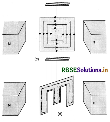
If the same experiment is repeated by a slotted plate Fig. LAQ 8 (d) the motion of plate is not much affected by the magnetic field because eddy currents are reduced as the same closed loop has a much longer path as shown by dotted closed line in Fig.(d). Longer path means more resistance, hence eddy currents will be reduced.
In a transformer the changing magnetic flux produces eddy currents in the iron core of the transformer and leads to the wastage of energy in the form of heat. This wastage of energy can be minimised by using a laminated iron core.
To minimize the eddy currents
To minimize the heating and breaking effect of eddy currents, the desired iron or metal frame to be used in the appliance is taken in the form of thin sheets, each one of which is electrically insulated from the other. Further the sheets are so adjusted that their planes are perpendicular to the direction of currents which would be set up by the emf induced in the metal. As the insulation layers between the sheets offer large resistance and the area of the conductor is reduced, the eddy currents are thus reduced.
Application of eddy currents. Eddy currents have been put to the following important uses:
1. Speedometers. In a speedometer, a drum rotates according to the speed of the vehicle. The magnet is placed inside an aluminium drum which is carefully pivoted. When the magnet swings, it drags the drum also through a certain angle depending upon the speed of the vehicle.
2. Induction furnace. A metallic substance which is to be melted is placed in a high frequency magnetic field. Large eddy currents will be produced in the substance and so much heat is produced that it melts the substance. This arrangement is used to separate metal from its ore and some alloys of metal can be formed.
3. Dead beat Galvanometer. When steady (constant) current is passed through the coil of a galvanometer, it is deflected and oscillates about its equilibrium position for a long time. But if the same coil is wound over a metallic frame and as current is passed in the coil, eddy currents are produced in the metal frame which opposes the motion of the coil and makes it dead beat i.e. non-oscillatory. This is also called electromagnetic damping.
4. Damping. To stop the vibrations of ballistic galvanometer, the galvanometer is shunted by connecting external shunt resistance across whole of the coil. Smaller the shunt, greater are the eddy currents. The eddy currents thus damp the motion of ballistic galvanometers.
5. Induction motor. In an a.c. induction motor, a metallic cylinder is placed in the rotating magnetic field. Eddy currents are produced in the cylinder which try to decrease the relative motion between rotating magnetic field and the cylinder. As a result, the cylinder also starts rotating about its axis.
6. Magnetic brakes. When a train moves, the axis of the wheel also rotates. A drum attached to the axle also starts rotating. Whenever the train is required to be stopped, a magnetic field is applied to the rotating drum. The eddy current production in the drum apply upon it an opposing torque and as a result the train stops immediately.

Question 19.
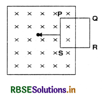
The closed loop PQRS is moving into a uniform magnetic field acting at right angles to the plane of the paper as shown in Fig. SAQ 19. State the direction in which the induced current flows in the loop.
Answer:
When the closed loop PQRS is moved into the uniform magnetic field, the magnetic flux linked with the coil will increase and induced e.mf. will be produced as predicted by Lenz’s law and the direction of induced current will act in such a way that it opposes the motion of the coil i.e. force on arm PS will be towards right hence the current in arm PS should be from P to S. Thus the induced current will be in the directions PSRQP.
Question 20.
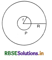
Two circular coils, one of radius r and other of radius R are placed coaxially with their centres S coinciding. For R >> r, obtain an expression for mutual inductance of the arrangement.
Answer:
If i is the current passing in the outer coil of radius R, then magnetic field at its centre.
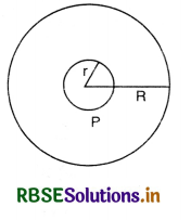
B = \(\frac{\mu_0}{4 \pi} \frac{2 \pi i}{\mathrm{R}}\)
∴ Magnetic flux through coil P
Φ = BA = \(\frac{\mu_0}{4 \pi} \cdot \frac{2 \pi i}{R}\left(\pi r^2\right)\)
= \(\frac{\mu_0}{4 \pi} \frac{2 \pi^2 i r^2}{\mathrm{R}}\)
∴ mutual inductance between the coils
M = \(\frac{\phi}{i}=\frac{\mu_0}{4 \pi} \cdot \frac{2 \pi^2 r^2}{\mathrm{R}}\)
Question 21.
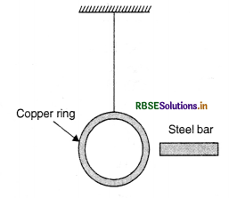
A copper ring is suspended in a vertical plane by a thread. A steel bar is passed through the ring in a horizontal direction and then a magnet is similarly passed through. Will the motion of the bar and the magnet affect the position of the ring?
Answer:
The motion of bar will not affect the position of the ring, but when magnet is passed, a current is induced in the ring which opposes the approach of the magnet i.e. repelled by it.
Question 22.
Explain why the inductance coils are made of copper.
Answer:
The resistance of copper is small, so induced current is large, hence coils are made of copper.
Question 23.
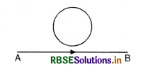
The magnitude of electric current is from A towards B. If there is any induced current in the loop as shown in the figure, what will be its direction?

Answer:
The direction of magnetic field produced by the current is perpendicular to the plane outward. So according to Lenz's law, the direction of induced current should produce magnetic field in the downward direction. This is possible if the direction of induced current in the loop is clockwise.

Question 24.
Coils of resistance boxes are made from doubled up insulated wire. Why?
Answer:
The coils are made from doubled up insulated wire to avoid inductive effect. The current flowing in two parts of the wire is opposite, hence total magnetic field is zero.
Question 25.
Why does the acceleration of a magnet falling through a long solenoid decrease?
Or
A small magnet falls through a metal ring. Will its acceleration be equal to g?
Answer:
When the magnet is allowed to fall freely, the magnetic flux linked with the solenoid increases and induced e.m.f. is produced in the solenoid. According to Lenz’s law, the direction of induced e.m.f. is such that it always opposes the cause (i.e. acceleration of magnet). Hence, the acceleration of magnet will be less than the acceleration due to gravity.
Question 26.
A rectangular coil of N turns and area of cross-section A, is held in time varying magnetic field. Deduce an expression for the e.m.f. induced in the coil.
Answer:
Here Φ = ANB
∴ e = \(-\frac{d \phi}{d t}=-\mathrm{AN} \frac{d \mathrm{~B}}{d t}\)
Question 27.
What are eddy currents? Give their two applications.
Or
What are eddy currents? How are they reduced?
Answer:
Eddy or Focault currents are the currents induced in the body of a conductor when the magnetic flux linked with the conductor changes.
Since i = \(\frac{e}{R}\)
But e = \(-\frac{d \phi}{d t}\)
∴ i = \(-\frac{d \phi / d t}{\mathrm{R}}\)
The direction of eddy currents is given by Lenz’s law or Fleming's left hand rule. Eddy currents are reduced by taking laminated sheets of metal instead of single plate.
Applications
1. Induction motor or a.c. motor.
A rotating magnetic field due to alternating current produces strong eddy current in a rotor which starts rotating in the direction of rotating magnetic field.
2. Induction furnace makes use of heating effect of electric currents. The substance to be melted (say to form alloys) is placed in a high frequency magnetic field. The strong eddy currents developed in the substance produces so much heat that it melts. Such an arrangement is called induction furnace.

Question 28.
Explain the production of eddy currents in a conductor.
Answer:
When a plate or anybody made of metal is moved in or out of a magnetic field or placed in any changing magnetic field, the amount of the flux linked with the plate changes and an induced e.m.f. is
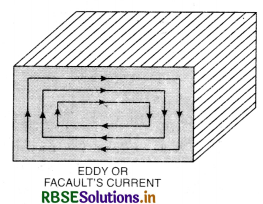
developed in the plate. The induced e.m.f. causes currents which flow in many closed paths throughout the body of the conductor in the same way as in a closed circuit placed in a varying magnetic field. Such currents are known as eddy currents. They are so called because they look like eddies or whirlpools. Eddy currents are used for making moving coil galvanometer dead beat. It is also used in induction motor, magnetic brakes, speedometer and induction furnaces etc.
Question 29.
Define coefficient of self induction. Give its unit.
Answer:
Coefficient of self induction of a circuit is equal to the magnetic flux linked with the circuit when unit current is passed through it. It is also equal to the back e.m.f. induced in the circuit when the current flowing through it is changing at the rate of unit current per second. It is represented by L and its unit is henry.
Question 30.
Define mutual inductance. State two factors on which the mutual inductance between given pair of coils depends.
Answer:
Mutual inductance is the property of two coils by virtue of which each opposes any change in the strength of the current flowing through the other by developing an induced e.m.f.
Coefficient of mutual inductance of two coils is numerically equal to the amount of magnetic flux linked with one coil when unit current flows through the neighbouring coil.
Mutual inductance depends upon:
- Geometry of coils i.e. number of turns, nature of the material on which wound; size and shape of the coils.
- distance between two coils.
- Orientation or relative placement of the coils.
Question 31.
How does the mutual inductance of a pair of coils get affected when
(i) distance between coils is increased?
(ii) the number of turns in each coil is decreased?
(iii) a thin iron sheet is placed between the two coils, other factors remaining the same? Explain your answer in each case?
Answer:
(i) Mutual inductance decreases with the increase of distance between the coils. This is due to loose coupling between the coils.
(ii) With the decrease of the number of turns, the mutual inductance decreases. The coupling between two coils is proportional to np ns, where np and ns are the number of turns in primary and secondary coils respectively. Hence mutual inductance decreases with the decrease in number of turns of the two coils.
(iii) When a thin iron sheet is placed between the two coils the permeability of the medium is increased many times, which results in increase of mutual inductance between the coils.

Question 32.
Suppose a helical spring is suspended from the roof and a very small weight is attached to its lower end. What will happen to the spring when the current is passed through it? Give reason to support your answer.
Answer:
The spring will contract.
Reason. We know that if current passes through a wire in clockwise direction, it behaves like South pole and if it flows in anticlockwise direction, it behaves like North pole.
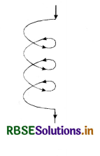
If we observe the enclosed figure, the current is flowing in anticlockwise direction when observed from above and clockwise if observed from below. Hence upper side will behave like north and lower like south pole. Whole of the coil will behave like N and S poles placed side by side and hence will attract each other resulting in contraction of the coil.
Question 33.
In the figure SAQ 12 (a) a bar magnet moving towards the right or left induces an e.m.f. in the coils (1) and (2). Find, giving reason, the direction of induced currents through resistors AB and CD. When the magnet is moving (a) towards the right and (b) towards the left.
Answer:
(a) When the magnet is moving towards right. When the magnet is moving towards right, the N pole of the magnet is moving away from coil (1) and is approaching towards coil (2), hence it forms S-pole in coil (1) (due to clockwise current) and the current is from A to B Fig. SAQ 12 (b) and S pole is also formed in coil (2). (due to induced clockwise current) and the current is from D to C.

(b) When the magnet is moving towards left. Here N-pole is approaching towards coil (1) and S-pole is receding away from coil (2), So N-pole is formed both in coil (1) and (2) as shown in Fig. 12 (c).

Question 34.
The figure SAQ 13 (a) a bar magnet M falling under gravity through an air cored coil. Plot a graph showing variation of induced e.m.f. with time (t). What does the area enclosed by E-t curve depict?
Answer:
The graph between E and t is as shown in Fig. SAQ 13 (b). Here as the magnet approaches the coil, E will go on increasing up to b. When the magnet fully enters the coil given by point c, there is no change in magnetic flux, it is shown by c in Fig. SAQ 13 (b).
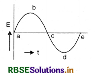
And again when it is coming out from the coil, the value of E increases in reverse direction.
Area below E-t graph gives the magnetic flux because
Et = flux [∵ \(\frac{d \phi}{d t}\) = E or dΦ = E dt]
Question 35.
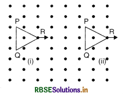
The given figure SAQ 35 shows the positions of a loop PQR in a perpendicular uniform magnetic field. In which position of the coil there is an induced e.m.f.
Answer:
In position (i) the loop PQR is inside the uniform magnetic field and there is no change in the magnetic field, hence no e.m.f. is produced.
In position (ii), the loop PQR is coming out of the magnetic field and there is decrease in magnetic flux and hence induced e.m.f. is produced in the loop.
Question 36.
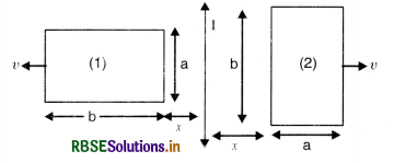
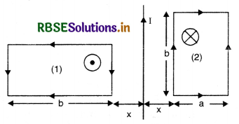
The figure SAQ 36 shows two identical rectangular loops (1) and (2) placed along with a straight long current carrying conductor between them.
(i) What will be the direction of induced currents in the loops when they are pulled away from the conductor with the same velocity v?
(ii) Will the e.m.f. induced in the two loops be equal?
Answer:
According to Fleming’s right hand rule, the magnetic field due to current I on loop (1) is vertically downward and perpendicular to the plane of paper and hence the current will be clockwise (Fig. SAQ 14 (b) and in loop (2), the magnetic field is directed outwards and perpendicular to the plane of paper and the current will be in anticlockwise direction as shown in Fig. SAQ 14 (b).
Question 37.
In a ceiling fan, each blade rotates in a circle of radius 0.5 m. If the fan makes 2 rotations per second and the vertical component of the earth’s magnetic field is 8 x 10⁻⁵ T, calculate the emf induced between the inner and outer ends of each blade.
Answer:
Here r = 0.5 m, v = 2 rps, B = 8 x 10⁻⁵ T, e = ?
∴ ω = 2πv = 2 x π x 2 = 4 π
∴ Induced emf. e = \(\frac{1}{2}\) Brv = \(\frac{1}{2}\) Brrω = \(\frac{\mathrm{B} r^2 \omega}{2}\)
= \(\frac{8 \times 10^{-5} \times(0.5)^2 4 \pi}{2}\)
e = 12.56 x 10⁻⁵ V

Question 38.
The closed loop PQRS is moving into a uniform magnetic field acting at right angles to the plane of the paper as shown in Fig 6.50 State the direction in which the induced current flows in the loop.
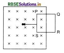
When the closed loop PQRS is moved into the uniform magnetic field, the magnetic flux linked with the coil will increase and induced e.mf. will be produced as predicted by Lenz’s law and the direction of induced current will act in such a way that it opposes the motion of the coil i.e. force on arm PS will be towards right hence the current in arm PS should be from P to S. Thus the induced current will be in the directions PSRQP.
Question 39.
Two circular coils, one of radius r and other of radius R are placed coaxially with their centres coinciding. For R >> r, obtain an expression for mutual inductance of the arrangement.
Answer:
If i is the current passing in the outer coil of radius R, then magnetic field at its centre.
B = \(\frac{\mu_0}{4 \pi} \frac{2 \pi i}{\mathrm{R}}\)
∴ Magnetic flux through coil P
Φ = BA = \(\frac{\mu_0}{4 \pi} \cdot \frac{2 \pi i}{R}\left(\pi r^2\right)\)
= \(\frac{\mu_0}{4 \pi} \frac{2 \pi^2 i r^2}{\mathrm{R}}\)
∴ mutual inductance between the coils
M = \(\frac{\phi}{i}=\frac{\mu_0}{4 \pi} \cdot \frac{2 \pi^2 r^2}{\mathrm{R}}\)
Question 40.
The magnitude of electric current is from A towards B. If there is any induced current in the loop as shown in the figure, what will be its direction?
Answer:
The direction of magnetic field produced by the current is perpendicular to the plane outward. So according to Lenz's law, the direction of induced current should produce magnetic field in the downward direction. This is possible if the direction of induced current in the loop is clockwise.
Question 41.
Define mutual inductance and write its SI unit.
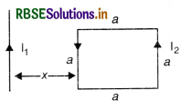
A square loop of side ‘a’ carrying a current I2 is kept at distance x from an infinitely long straight wire carrying a current I1 as shown in the figure SAQ 41. Obtain the expression for the resultant force acting on the loop.
Answer:
(a) Mutual inductance equals the magnetic flux associated with a coil when unit current flows in its neighbouring coil.
(b) Force per unit length between two parallel straight conductors
\(\frac{\mathrm{F}}{\mathrm{L}}=\frac{\mu_0 \mathrm{I}_1 \mathrm{I}_2}{2 \pi r}\)
Force on the part of the loop which is parallel to infinite straight wire and at a distance x from it
F1 = \(\frac{\mu_0 \mathrm{I}_1 \mathrm{I}_2 a}{2 \pi x}\) (away from the infinite long wire)
Force on the part of the loop which is at a distance (x + a) from it
F2 = \(\frac{\mu_0 \mathrm{I}_1 \mathrm{I}_2 a}{2 \pi(x+a)}\)
(towards the infinite long wire)
Net force, Fnet = F1 - F2
Fnet = \(\frac{\mu_0 \mathrm{I}_1 \mathrm{I}_2 a^2}{2 \pi(x+a)}\)
(away from the infinite straight line)

Question 42.
How does the mutual inductance of a pair of coils affected when
(i) distance between coils is increased?
(ii) the number of turns in each coil is decreased?
(iii) a thin iron sheet is placed between the two coils, other factors remaining the same? Explain your answer in each case.
Answer:
(i) Mutual inductance decreases with the increase of distance between the coils. This is due to loose coupling between the coils.
(ii) With the decrease of the number of turns, the mutual inductance decreases. The coupling between two coils is proportional to np ns, where np and ns are the number of turns in primary and secondary coils respectively. Hence mutual inductance decreases with the decrease in number of turns of the two coils.
(iii) When a thin iron sheet is placed between the two coils the permeability of the medium is increased many times, which results in increase of mutual inductance between the coils.
Question 43.
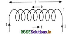
Deduce an expression for the self inductance of a long solenoid of N turns, having a core of relative permeability µr.
Answer:
Expression for coefficient of self inductance for a Solenoid:
Consider a solenoid of length l
Let r = radius of solenoid such that r < l
n = no. of turns per unit length
I = strength of current through the solenoid
The magnetic field produced by the current inside the solenoid is practically constant and B = µ0 nI
∴ Magnetic flux linked with the loop,
dΦ = µ0 n IA
Magnetic flux linked with entire solenoid
Φ = nl(µ0 n IA) = µ0n2lAI
Since Φ = LI
∴ LI = µ0 n2 l A
L = µ0 n2 l A
If the coil is wound on a material having relative permittivity µr
then L = µ0 µr n2 l A
Question 44.
Give the direction in which the induced current flows in the coil mounted on an insulated stand, when a bar magnet is quickly moved along the axis of the coil from one side to the other as shown in the figure.
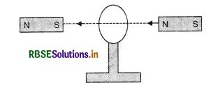
Answer:
When the magnet moves towards the coil as observed from the right, the direction of current is clockwise and when the magnet moves away from the coil and is seen from the right, the direction of current is anticlockwise.
Question 45.
A small magnet falls through a metal ring. Will its acceleration be equal to g?
Answer:
When the magnet is allowed to fall freely, the magnetic flux linked with the solenoid increases and induced e.m.f. is produced in the solenoid. According to Lenz’s law, the direction of induced e.m.f. is such that it always opposes the cause (i.e. acceleration of magnet). Hence, the acceleration of magnet will be less than the acceleration due to gravity.
Question 46.
Twelve wires of equal lengths are connected in the form of a skeleton cube which is moving with a velocity \(\vec{v}\) in direction of magnetic field \(\vec{v}\). Find the e.m.f. in each arm of the cube.
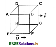
Answer:
The induced e.m.f. is given by
e = Blv sin θ
For horizontal conductors, θ = 0, so e = 0
Now the magnetic flux produced in the vertical conductors passes through the empty portion of the coil and hence no induced e.m.f. is produced.

Question 47.
(a) Define self inductance. Write its SI units.
(b) Derive an expression for self inductance of a long solenoid of length l, cross-sectional area A having N number of turns.
Answer:
(a) Self induction. The phenomenon according to which an opposing emf is induced in a coil as a result of varying current in the coil itself is called self induction. The emf produced in coil is also called back emf.
The effect of self-induction in an electric circuit is similar to the inertia of motion, therefore, it is called electric inertia.
(b) Coefficient of self induction. The magnitude of the magnetic flux through a coil due to its own current depends on the strength of the current and the shape and size of the circuit.
If I = strength of the current
and Φ = magnetic flux linked with the circuit,
we have
Φ ∝ I
or Φ = L I
This constant, L, is called the coefficient of self induction or simply self inductance of the circuit.
If I = 1, unit of current Φ = L
From this, the coefficient of self-inductance may be defined as follows:
The self inductance or coefficient of self induction of a circuit is equal to the magnetic flux linked with circuit when unit current is flowing in it.
Another definition of L
e = \(-\frac{d \phi}{d t}\)
or e = \(-\frac{d(\mathrm{LI})}{d t}=-\mathrm{L} \frac{d I}{d t}\)
The negative sign indicates that the direction of the induced emf opposes the change in magnetic flux.
If \(\frac{d \mathrm{I}}{d t}\) = 1
Then e = L (numerically)
The self inductance or the coefficient of self-induction of a circuit is equal to the emf induced in the circuit when the current flowing through it is unity.
Unit of Self-inductance. As stated above
e = -L\(\frac{d \mathrm{I}}{d t}\)
In SI unit, if e = 1 volt
and \(\frac{d \mathrm{I}}{d t}\) = 1 A s-1, then L = 1 henry (H).
Hence, the self inductance of a coil is (1) henry if a change of current equal to 1 ampere per second causes an induced emf equal to one volt in the circuit.
(c) Expression for Coefficient of self-induction for a Solenoid
Consider a solenoid of length l
Let r = radius of solenoid such that r < l
n = no. of turns per unit length
I = strength of current through the solenoid
The magnetic field produced by the current inside the solenoid is practically constant and B = µ0 nI
∴ Magnetic flux linked with the loop,
dΦ = µ0 n IA
Magnetic flux linked with entire solenoid
Φ = nl (µ0 n IA) = µ0 n2lAI
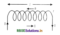
Since Φ = LI
∴ LI = µ0n2 l I A
L = µ0 n2 l A ................................(i)
If the coil is wound on a material having relative permittivity µr
then L = µ0 µr n2 l A
(d) Examples of self induction
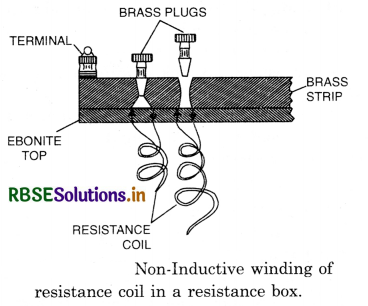
(1) Non-inductive coils. In electrical measurements, we have to make use of resistance boxes, post office boxes and other bridges. In these instruments, inductance is a nuisance. To minimize the inductive effect, this is done by double backing the resistance wire on itself by winding it on the same bobbin. The free ends of the wire are connected to binding screws of the box. Fig. shows a non-inductive coil. Note that every part of the coil is traversed by two opposite currents. The magnetic field due to the current in one part is opposed by that in the other. The total field is negligible. Hence, the coil becomes non-inductive.
(2) Electromagnetic damping. When some current is passed through a galvanometer coil, it suffers a few to and fro oscillations about its final equilibrium position before settling down. As the coil gets deflected, it moves in the magnetic field and. therefore, an induced emf is produced in the coil which opposes its motion. It is thus the electromagnetic induction which is mainly responsible for the damping of the galvanometer.
If N = total number of turns, then
N = nl
or n = \(\frac{\mathrm{N}}{l}\)
So the equations L = M0n2lA becomes
L = \(\frac{\mu_0 \mathrm{~N}^2 \mathrm{~A}}{l}\)
Long Answer Type Questions
Question 1.
Define electromagnetic induction, magnetic flux linked with a given area and magnetic induction. What are their units? When is magnetic flux taken (i) positive and (ii) negative. Find dimensional formula of Φ.
Answer:
Electromagnetic induction
Electromagnetic induction may be defined as the phenomenon of production of electric current (or e.m.f.) in a closed coil (or circuit), when magnetic flux linked with the coil (or circuit) is changed.
Magnetic flux (Φ). The total number of lines of induction passing normally through a given area is called magnetic flux.
Consider a surface A. Take a small element of area dA. If \(\vec{B}\) makes an angle θ with the area vector \(d \vec{A}\), then magnetic flux linked with area dA will be
dΦ = \(\vec{B}.d \vec{A}\)
(where area vector \(d \vec{A}\) is a vector having magnitude dA and direction normal to dA.)
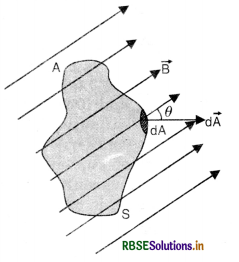
Total magnetic flux linked with the whole surface S will be
Φ = \(\int \overrightarrow{\mathrm{B}} \cdot d \overrightarrow{\mathrm{A}}\)
If the surface is plane and having area S, then
Φ = \(\vec{B}.\vec{A}\)
or Φ = BA cos θ ...........................(1)
Units of Φ
If B = 1T, A = 1m2, θ = 0°, then Φ = 1Wb. Hence magnetic flux is said to be 1 weber (1Wb) if a magnetic field of 1 tesla is normal to the area of 1 m2. So 1Wb = 1T m2
Magnetic induction (B). It is defined as the magnetic flux associated per unit area.
i.e. B = \(\frac{\phi}{\mathrm{A}}\)
Units. In S.I. the unit of B is Wb m2 or tesla (T).
Positive and negative flux
Since Φ = BA cos θ
So (I) If θ > 90°, Φ = -ve (i.e. Φ is inward the surface)
(II) If θ < 90°, Φ = +ve (i.e. Φ is outward to the surface)
(III) If θ = 90°, Φ = BS (i.e. maximum flux.)
Dimensional formula of Φ
Φ = BA cos θ = \(\frac{\mathrm{FA}}{q v}\) cos θ [∴ F = q B v]
= \(\frac{\left[\mathrm{MLT}^{-2}\right]\left[\mathrm{L}^2\right]}{[\mathrm{AT}]\left[\mathrm{LT}^{-1}\right]}\) = [ML2T-2A-1]

Question 2.
(a) State Faraday's laws of electro-magnetic induction.
(b) Illustrate the phenomenon of E.M.I. by Faraday's experiments.
(c) What is the cause of electro-magnetic induction?
Answer:
(a) Faraday's laws of electromagnetic Induction. Faraday gave the following two laws of E.M.I.
(i) First law. Whenever magnetic flux linked with a closed circuit changes, an induced e.m.f. (or current) is produced and it lasts so long as the change in magnetic flux continues.
(ii) Second law. The magnitude of induced e.m.f. is directly proportional to the rate of change of magnetic flux linked with the circuit.
Mathematically,
If Φ1 = magnetic flux linked with coil at time = 0
Φ2 = magnetic flux linked with the coil at time = t,
then,
Rate of change of magnetic flux
= \(\frac{\phi_2-\phi_1}{t-0}=\frac{\phi_2-\phi_1}{t}\)
∴ Induced e.m.f. e ∝ \(\frac{\phi_2-\phi_1}{t}\)
or e = -k(\(\frac{\phi_2-\phi_1}{t}\)),
where k is constant of proportionality and -ve sign means the opposing nature of induced e.m.f. and k = 1 (for all systems)
∴ e = -(\(\frac{\phi_2-\phi_1}{t}\)) ........................(1)
If the change in magnetic flux is in small amount dΦ in time dt, then
e = -\(\frac{d \phi}{d t}\)
If the coil has N turns, then
e = -N (\(\frac{\phi_2-\phi_1}{t}\)) = -N\(\frac{d \phi}{d t}\)
(b) Experiment 1. Current induced by the action of magnets on closed circuits. Consider a coil of insulated copper wire wound on a cardboard tube. Place the coil upright and connect the ends of the wire to a sensitive centre zero galvanometer. If the north pole of a bar magnet is now quickly inserted into the coil [Fig. 2 (a)], a momentary deflection will be observed in the galvanometer, say towards right. On withdrawing the magnet, the galvanometer gives kick in the opposite direction, i.e., towards left [Fig. 2 (b)].
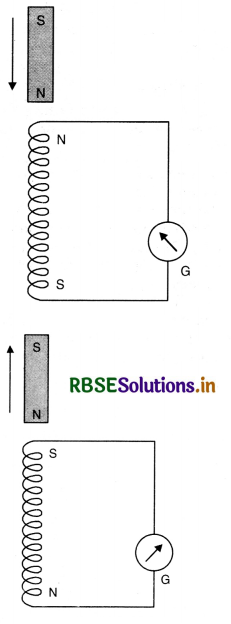
The above experiment may be repeated by first pushing the south pole into the coil and then withdrawing it. In both the cases, it will be observed that galvanometer shows deflection in directions opposite to those when the north pole was facing the coil. It is further found that if the magnet is held stationary anywhere near or inside the coil, galvanometer does not show any deflection. Identical results are obtained if the magnet is kept stationary and the coil is moved towards or away from the magnet. The above experiments prove that a current appears in the coil only when there is relative displacement between the coil and the magnet. The e.m.f. produced in a coil by the above method is called induced e.m.f. When the galvanometer circuit is closed, the induced e.m.f. drives current, called induced current, along the circuit.
Experiment 2. Currents induced by currents. Take two coils each consisting of several turns of copper wire and place them coaxially close together as shown in Fig. Connect a battery and tapping key across the two ends of the coil P1P2 and a galvanometer across S1S2. The coil P1P2 containing a battery is usually called primary and the second coil S1S2 is called secondary.
It will be observed that when tapping key is pressed, the galvanometer shows a momentary deflection. When the key is released, again a momentary deflection, but in the opposite direction, will be observed. However, if the key is kept pressed and a steady current flows through P1P2, the galvanometer will show no deflection.
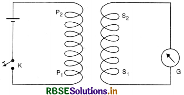
If instead of making and breaking the primary current, if the strength is changed, induced current is still observed in the secondary. When the strength of current in primary is increased, an induced current is set up in the secondary and its direction is opposite as that of a make. Similarly, when the primary current is diminished, an induced current, whose direction is the same that at break is produced in the secondary.
(c) Cause of Induced E.M.F.
It is observed that an induced e.m.f. or current is produced if a magnet is moved in or out of a coil, In Figure LAQ 2 (d,e) the magnetic flux linked with the various turns of the coil changes. When the magnet is moved into the coil, the flux linked with the circuit will however be different for any other position of the magnet with respect to the coil. Thus, with the motion of the magnet into the coil, the flux linked with the circuit increases. If the magnet is moved out of the coil, the flux will evidently decrease. Therefore, by moving a magnet into or out of the coil, the flux changes (i.e. increases or decreases). Hence, we infer that it is the change in the flux linked with the coil which is responsible for the production of induced e.m.f. This phenomenon of production of an electric current in circuit by changing the flux associated with it is called electromagnetic induction.
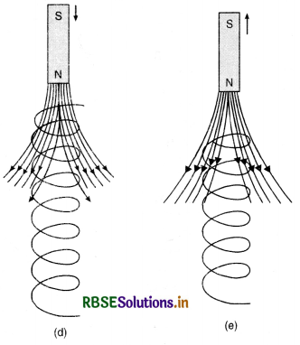
Similarly in experiment II, in passing the current and releasing the key at the time of break, magnetic flux again changes and hence induced current is produced.

Question 3.
State Lenz's law and illustrate it with experiment.
Answer:
Lenz’s law. It states that the direction of induced current (or e.m.f.) is such that it always opposes the cause producing it. This law gives the direction of an induced current in terms of the cause of the current. An induced current in a coil is always due to change of magnetic flux linking the coil. The induced current will have its own associated magnetic flux. This law means to say that this magnetic flux of induced current will be such as to oppose the change of the primary magnetic flux.
Experimental verification of Lenz’s law
Let us connect the two ends of a coil of few turns to a cell C and a galvanometer G through a two way key having terminals 1, 2 and 3 as shown in Fig,
Put the plug between gap 1 and 2, the current in the upper face of the coil is in anticlockwise direction of N-pole is produced on this upper face. Let the galvanometer shows deflection to the right side.
Now remove the key from gaps 1 and 2 and insert between 2 and 3, so the cell C is cut off. Bring N-pole of a bar magnet towards the upper face of the coil, the deflection produced in the galvanometer is again towards right. It means that the upper face of the coil becomes N-pole and repels the incoming magnet. Now take the magnet away from the coil, the deflection in the galvanometer is now towards left i.e. S-pole is formed at the upper end of the coil and it attracts the N-pole of the magnet.
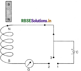
Thus we find that whether the magnet is taken towards or away from the coil, the direction of induced e.m.f. is such that it always opposes the motion of the magnet as predicted by Lenz’s law.

Question 4.
Show that Lenz's law is direct consequence of law of conservation of energy.
Answer:
No, Lenz's law does not violate the principle of conservation of energy. When we move a magnet (say N-pole) towards a coil, the end of coil nearer to the magnet acquires the same polarity (N-pole) and hence opposes the motion of magnet Fig. LAQ 4 (a). So work has to be done against this force of repulsion in moving the magnet close to the coil.
Similarly, when the magnet (say N-pole) is moved away from the coil, the end of coil nearer to the magnetic pole acquires opposite polarity (S-pole) and
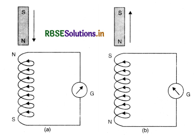
pulls the magnet towards it [Fig. (b)] and again work has to be done against the force of attraction in taking the magnet away from the coil. It is this mechanical work done by outside agency, on the magnet which is stored in the coil in the form of electrical energy. Hence Lenz’s law obeys the law of conservation of energy.
Question 5.
Explain electromagnetism induced by Lorentz force.
Or
A conducting rod of length l is moved in a magnetic field of magnitude B with velocity v such that the arrangement is mutually perpendicular. Prove that the e.m.f. induced in the rod is |E| = Blv.
Answer:
(i) Motion of conduction wire in a magnetic field. Imagine a small piece of metal wire being dragged across in between the pole pieces of a magnet as shown in Fig. LAQ 5 (a). A conductor consists of large no. of free electrons. These electrons can move freely inside the metal under the slightest force. The electrons in the metal wire will move along the wire, and direction of force acting on electron is given by equation
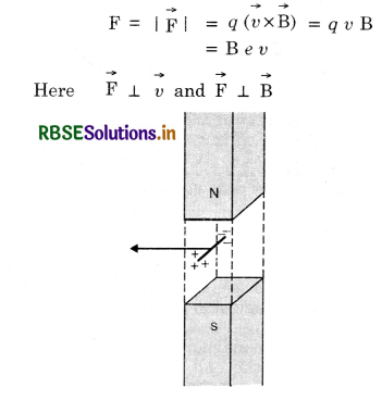
Net positive and negative charges will accumulate at the ends of the wire creating an electric field that will cause a force on the electrons in a direction that is opposite to the direction of the Lorentz force. Clearly, when a certain amount of accumulation of charges has taken place such that the electric force and the magnetic Lorentz force cancel, there will be no further movement of the ‘free’ electrons. The two ends of the wire thus become like the two terminals of a battery without any external connection.
Let V = P.D or induced e.m.f. developed across the ends of the conductor
∴ Electric field,
E = \(\frac{\mathrm{V}}{\mathrm{l}}\)
Force on electron due to electric field
F' = eE = \(\frac{e \mathrm{~V}}{l}\)
But F' = F
\(\frac{e \mathrm{~V}}{l}\) = B e v
∴ V = B l v
This is the e.m.f. induced across the two ends of the conductor.
(ii) A closed loop moving completely in magnetic field. Fig. LAQ 5 (b) shows a closed rectangular loop PQRS of metallic wire held horizontally in a uniform magnetic field \(\vec{B}\) acting ⊥ to the plane of the loop.
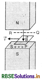
When the loop is dragged horizontally to the left with a velocity v, Lorentz force acts on the electrons in arms PQ and RS. Therefore, negative charges accumulate on QR and positive charges accumulate on PS, assuming that the loop is completely within the magnetic field. Though QR and PS are connected by conducting wires PQ and RS yet no flow is possible because a continuous path for the flow of electrons is not available, Fig. (b).
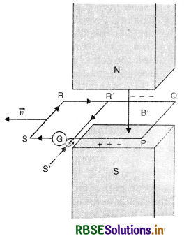
(iii) A closed loop moving partially in a magnetic field. Suppose a part PQR'S' is inside the magnetic field and portion R'S'SR is just outside the field. R'S' is another wire connecting QR and PS, Fig. 661 (c). The negative charges accumulated on R' and positive charges accumulated on PS find a conducting path S'SRR’S’ for their continuous flow. Therefore, current begins to flow in this loop as is indicated by galvanometer G. This is the induced current.

Question 6.
Discuss the motion of a straight conductor in a uniform magnetic field and derive an expression for the induced e.m.f. set in it. Also show that the induced e.m.f. is numerically equal to the rate of change of magnetic flux.
Answer:
Consider a loop ABCD placed in a uniform magnetic field of strength B. Suppose the arm CD can slide in the direction shown. On sliding, there will be an induced e.m.f. and thus a current along ABCD. Consider an electron in CD, which has drift velocity, say \overrightarrow{v_d} along DC in addition to v. The velocity v is perpendicular to vd. The magnetic Lorentz force on the electron has two components therefore: e vdB along DC and e vd B in direction opposite to v. The electron acceleration along DC on account of the force evB is opposed by the average force due to collisions with atoms, resulting in a net zero force along DC but a constant, drift velocity vd. This is just like the steady current which results when forces act on electrons in a conductor due to electric fields. The force e vd B will of course cause the electrons to strike the left edge of the conductor exerting a force, say of magnitude F on it. The conductor reacts with an opposite force F on the electron. Since the electron finally is unaccelerated, F must equal evd B. The agent pulling CD is obviously having to work against the force F exerted on CD. In a small time interval ∆t, the work done by the agent is
dW = Force x distance travelled in ∆t
= e vd B dl ........................(1)
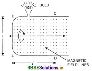
The electron moves through a distance dl = vd dt in time dt and hence
dW = e. vd B dl ..................(2)
This is the work done by the agent in pulling CD during which a charge has moved through the distance dl. The work done by the agent during the time over which a unit charge moves along the entire length of CD is then:
W = vd.B.l = B vd l = B \(\frac{d l}{d t}\).l
W = B\(\frac{d l^2}{d t}\)
= B\(\frac{d A}{d t}\) (A = l2 = area of loop)
or W = Φ .......................(3)
W is clearly the e.m.f. e across the entire loop since CD is the only moving part of the loop. Eq. (3) is thus the same as Faraday’s flux rule.

Question 7.
What is the difference between electric field produced by stationary charges and moving charges?
Or
What are conservative and non-conservative fields?
Answer:
Consider a closed loop in which a current is flowing. The fact that a current is flowing implies of- course that an electric field E exists along the loop.
Small amount of work done in moving a unit charge through dl is given by -\(\overrightarrow{\mathrm{E}} \cdot\) \(\overrightarrow{d l}\).
When the work done in taking unit charge along the entire closed loop is emf = \(\oint \overrightarrow{\mathrm{E}} \cdot \overrightarrow{d l}\)
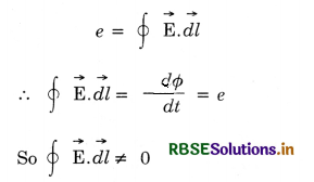
Such fields are called non-conservation fields.
-\(\oint \overrightarrow{\mathrm{E}} \cdot \overrightarrow{d l}=-\frac{d \phi}{d t}\), .................................(1)
where Φ is the flux across the loop
Consider in constant, an electric field caused by a charge at rest. If we take a unit charge from point a to point b, such field has the property that the work done
Wab = -\(\int_a^b \overrightarrow{\mathrm{E}} \cdot \overrightarrow{d l}\) .......................(2)
is independent of the path taken from a to b. If charge is taken along a closed path
\(\oint \overrightarrow{\mathrm{E}} \cdot \overrightarrow{d l}\) = 0 ............................(3)
This last equation is different from (2). The electric fields created by changing magnetic field thus have a somewhat different character when compared to electric fields due to stationary charges.
The field where the closed line integral of electric field is zero (\(\oint \overrightarrow{\mathrm{E}} \cdot \overrightarrow{d l}\) = 0) is called conservative field.
Question 8.
What are eddy currents? How are they minimised? What uses are they put to?
Or
What are eddy currents? How are these produced? In what sense are the eddy currents considered undesirable in transformer and how are these reduced in such devices?
Answer:
Eddy current. When a solid conductor moves across a magnetic field or is placed in a changing magnetic field, the flux linked with the conductor changes and, therefore, induced (circulating) currents are set up in the conductor. In accordance with Lenz’s law, the direction of the induced currents opposes the motion of the conductor or the charges in the field to which they are due. Such circulating currents are called Focault's currents or eddy currents. Since the resistance of metal piece is quite low, these currents may be quite large and may produce heating or damping effects. Fig. LAQ 8 (a).
Thus eddy currents are the current induced in a conductor, when placed in changing magnetic field.
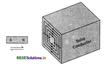
Magnitude of eddy current
I = \(\frac{\text { Induced e.m.f }(e)}{\text { Resitance }(\mathrm{R})}=\frac{e}{\mathrm{R}}\)
Since e = -\(\frac{d \phi}{d t}\)
∴ I = -\(\frac{d \phi / d t}{\mathrm{R}}=-\frac{1}{\mathrm{R}} \frac{d \phi}{d t}\)
The direction of I is given by Lenz’s law or Fleming’s right hand rule.
Note. Fleming’s Right Hand Rule
It states that if we stretch the first finger, central finger and thumb of our right hand in mutually perpendicular directions such that the first finger points along the direction of magnetic field and the thumb along the direction of motion of the conductor, tfien central finger would gives us the direction of induced e.m.f.
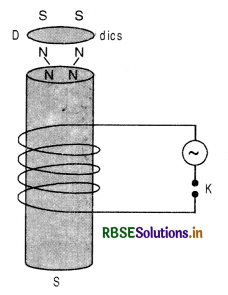
Illustrations
(i) If a light metallic disc D is placed at top of an electromagnet as shown in Fig. LAQ 8 (b) and a.c. is passed through the coil, the disc is thrown up due to eddy currents.
Explanation. On passing the current in the coil, the magnetic flux linked with the coil starts growing and thus magnetic flux linked with the solenoid and hence with the disc also increases and induced current is produced in the disc which converts it into a small magnet. The upper end of the iron core and lower face of the disc acquire the same polarity in accordance with Lenz’s law and due to repulsion between the upper end of soft iron and lower face of disc D, the disc is thrown up.
(ii) A simple pendulum is made of sheet of copper as shown in Fig. LAQ 8 (c). It is made to oscillate between the pole piece of an electromagnet. When the magnetic field is off, the metal plate oscillates freely for a long time. But when the magnetic field is switched on, the motion of the plate is damped due to production of eddy currents, because when the metal plate is displaced towards any one extreme position the area of the plate in the field decreases and magnetic flux linked with the plate decreases and eddy currents are produced which opposes the motion of the plate and thus produces damping. If the strength of magnetic field is very high, the plate is unable to move in the magnetic field and its motion becomes dead beat.
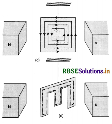
If the same experiment is repeated by a slotted plate Fig. LAQ 8 (d) the motion of plate is not much affected by the magnetic field because eddy currents are reduced as the same closed loop has a much longer path as shown by dotted closed line in Fig.(d). Longer path means more resistance, hence eddy currents will be reduced.
In a transformer the changing magnetic flux produces eddy currents in the iron core of the transformer and leads to the wastage of energy in the form of heat. This wastage of energy can be minimised by using a laminated iron core.
To minimize the eddy currents
To minimize the heating and breaking effect of eddy currents, the desired iron or metal frame to be used in the appliance is taken in the form of thin sheets, each one of which is electrically insulated from the other. Further the sheets are so adjusted that their planes are perpendicular to the direction of currents which would be set up by the emf induced in the metal. As the insulation layers between the sheets offer large resistance and the area of the conductor is reduced, the eddy currents are thus reduced.
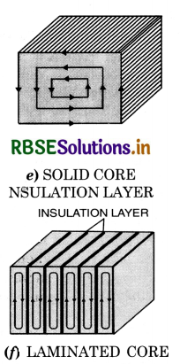
Application of eddy currents. Eddy currents have been put to the following important uses:
1. Speedometers. In a speedometer, a drum rotates according to the speed of the vehicle. The magnet is placed inside an aluminium drum which is carefully pivoted. When the magnet swings, it drags the drum also through a certain angle depending upon the speed of the vehicle.
2. Induction furnace. A metallic substance which is to be melted is placed in a high frequency magnetic field. Large eddy currents will be produced in the substance and so much heat is produced that it melts the substance. This arrangement is used to separate metal from its ore and some alloys of metal can be formed.
3. Dead beat Galvanometer. When steady (constant) current is passed through the coil of a galvanometer, it is deflected and oscillates about its equilibrium position for a long time. But if the same coil is wound over a metallic frame and as current is passed in the coil, eddy currents are produced in the metal frame which opposes the motion of the coil and makes it dead beat i.e. non-oscillatory. This is also called electromagnetic damping.
4. Damping. To stop the vibrations of ballistic galvanometer, the galvanometer is shunted by connecting external shunt resistance across whole of the coil. Smaller the shunt, greater are the eddy currents. The eddy currents thus damp the motion of ballistic galvanometers.
5. Induction motor. In an a.c. induction motor, a metallic cylinder is placed in the rotating magnetic field. Eddy currents are produced in the cylinder which try to decrease the relative motion between rotating magnetic field and the cylinder. As a result, the cylinder also starts rotating about its axis.
6. Magnetic brakes. When a train moves, the axis of the wheel also rotates. A drum attached to the axle also starts rotating. Whenever the train is required to be stopped, a magnetic field is applied to the rotating drum. The eddy current production in the drum apply upon it an opposing torque and as a result the train stops immediately.

Question 9.
(a) Explain the phenomenon of self induction.
(b) Define coefficient of self-induction and give its unit.
(c) What is the value of L for a solenoid?
(d) Give some practical applications of self inductance.
Answer:
(a) Self induction. The phenomenon according to which an opposing emf is induced in a coil as a result of varying current in the coil itself is called self induction. The emf produced in coil is also called back emf.
The effect of self-induction in an electric circuit is similar to the inertia of motion, therefore, it is called electric inertia.
(b) Coefficient of self induction. The magnitude of the magnetic flux through a coil due to its own current depends on the strength of the current and the shape and size of the circuit.
If I = strength of the current
and Φ = magnetic flux linked with the circuit,
we have
Φ ∝ I
or Φ = L I
This constant, L, is called the coefficient of self induction or simply self inductance of the circuit.
If I = 1, unit of current Φ = L
From this, the coefficient of self-inductance may be defined as follows:
The self inductance or coefficient of self induction of a circuit is equal to the magnetic flux linked with circuit when unit current is flowing in it.
Another definition of L
e = \(-\frac{d \phi}{d t}\)
or e = \(-\frac{d(\mathrm{LI})}{d t}=-\mathrm{L} \frac{d I}{d t}\)
The negative sign indicates that the direction of the induced emf opposes the change in magnetic flux.
If \(\frac{d \mathrm{I}}{d t}\) = 1
Then e = L (numerically)
The self inductance or the coefficient of self-induction of a circuit is equal to the emf induced in the circuit when the current flowing through it is unity.
Unit of Self-inductance. As stated above
e = -L\(\frac{d \mathrm{I}}{d t}\)
In SI unit, if e = 1 volt
and \(\frac{d \mathrm{I}}{d t}\) = 1 A s-1, then L = 1 henry (H).
Hence, the self inductance of a coil is (1) henry if a change of current equal to 1 ampere per second causes an induced emf equal to one volt in the circuit.
(c) Expression for Coefficient of self-induction for a Solenoid
Consider a solenoid of length l
Let r = radius of solenoid such that r < l
n = no. of turns per unit length
I = strength of current through the solenoid
The magnetic field produced by the current inside the solenoid is practically constant and B = µ0 nI
∴ Magnetic flux linked with the loop,
dΦ = µ0 n IA
Magnetic flux linked with entire solenoid
Φ = nl (µ0 n IA) = µ0 n2lAI
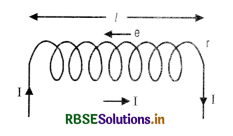
Since Φ = LI
∴ LI = µ0n2 l I A
L = µ0 n2 l A ................................(i)
If the coil is wound on a material having relative permittivity µr
then L = µ0 µr n2 l A
(d) Examples of self induction
(1) Non-inductive coils. In electrical measurements, we have to make use of resistance boxes, post office boxes and other bridges. In these instruments, inductance is a nuisance. To minimize the inductive effect, this is done by double backing the resistance wire on itself by winding it on the same bobbin. The free ends of the wire are connected to binding screws of the box. Fig. shows a non-inductive coil. Note that every part of the coil is traversed by two opposite currents. The magnetic field due to the current in one part is opposed by that in the other. The total field is negligible. Hence, the coil becomes non-inductive.
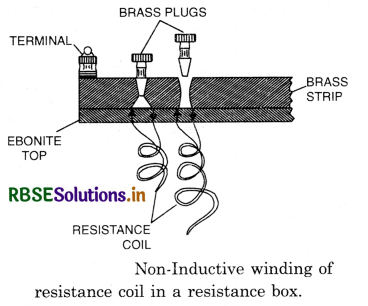
(2) Electromagnetic damping. When some current is passed through a galvanometer coil, it suffers a few to and fro oscillations about its final equilibrium position before settling down. As the coil gets deflected, it moves in the magnetic field and. therefore, an induced emf is produced in the coil which opposes its motion. It is thus the electromagnetic induction which is mainly responsible for the damping of the galvanometer.

Question 10.
(a) Define mutual induction and explain it.
(b) Define coefficient of mutual inductance. Give its units.
(c) Show that coefficient of mutual induction for one coil due to current in the other coil always remains the same.
Answer:
(a) Mutual induction. The phenomenon of producing an induced current in a coil or circuit by changing current in a neighbouring circuit, is called mutual induction.
Illustration
Consider two coils P1P2 and S1S2 placed close to each other. Coil P1P2 connected to battery and key k are called primary coils.
The coils S1S2 connected to galvanometer are called secondary coils.
When key k is inserted, the current starts increasing from zero to maximum. The magnetic flux linked to P1P2 also increases from zero to maximum. The magnetic flux passing through S1S2 also changes producing induced current in secondary.
According to Lenz’s law, the direction of current in the secondary coil at the time of make is in a direction opposite to battery current in the primary.
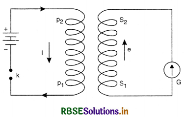
As the key is removed, the current in the primary decreases from maximum to zero, the magnetic flux linked with primary and hence with secondary also decreases from maximum to zero. The induced current will again be set up in the circuit the direction of which will be the same as that of battery current at the time of make.
(b) Coefficient of Mutual induction
It measures the ability of one coil to oppose the change in current in the neighbouring coil.
It is found that in a pair of coil, the magnetic flux Φ linked with one coil (secondary) is proportional to the current I flowing in the neighbouring (primary) coil.
i.e. Φ ∝ I
or Φ = MI .........................(1)
where M is the constant of proportionality and is called coefficient of mutual induction or mutual inductance of two coils.
If I = 1, then Φ = M
or M = Φ
i.e. in a pair of coils, the mutual inductance or coefficient of mutual induction numerically equal to the magnetic flux linked with one coil, when unit current is passed in the neighbouring coil.
Another definition of M
Also, induced e.m.f. e produced in the secondary coil is given by
e = \(\frac{d \phi}{d t}=-\frac{d}{d t}(MI)\)
= -M\(\frac{d \mathrm{I}}{d t}\)
or M = -\(\frac{e}{d \mathrm{I} / d t}\)
If dI/dt = 1, then M = -e ........................(2)
Hence, mutual inductance or coefficient of mutual induction, in a pair of coils is numerically equal to induced e.m.f. produced in a coil when current in the neighbouring coil is changing at the unit rate.
Units of coefficient of mutual induction or mutual inductance
We know that
M = \(\frac{e}{d \mathrm{I} / d t}\) (numerically)
(i) In S.I.
If e = 1 V, \(\frac{d \mathrm{I}}{d t}\) = 1 A s-1,
then M = 1 H (henry)
So, mutual inductance in a pair of coils is said to be 1 henry, if a current changing at the rate of 1 ampere/second in one coil induces an e.m.f. of 1 V in the neighbouring coil.
(c) Mutual Inductance of two solenoids
Consider two large solenoids A and B each of the length l such that solenoid A surrounds B.
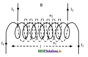
Let n1 = No. of turns per unit length of A
I1 = strength of current in A.
n2 = No. of turns per unit length of B.
I2 = strength of current in B
The axes of two solenoids are kept parallel.
It is assumed that magnetic field produced inside the solenoid is uniform and outside it, is zero.
Magnetic flux linked with inner solenoid due to current in outer solenoid is
Φ2 = µ0 x Magnetic field x Area x No. of turns
or Φ2 = µ0 n1 I1 x a x n2 I.
Comparing with equation
Φ2 = MBA I1
where MBA = coefficient of mutual induction of B when current is through A
MBA = µ0 n1 n2 la ...........................(1)
Now consider flux linked with outer solenoid A due to I2
The magnetic field due to I2 is constant inside the inner solenoid B but zero in the annular region between two solenoids.
∴ Φ1 = µ0 n1 I2 an2 l
Again Φ1 = MAB I2
∴ MAB = µ0 n1 n2 la .................................(2)
Comparing (1) and (2),
MBA = MAB = M (say)
Hence, coefficient of mutual induction between two long solenoids,
M = µ0 n1 n2 la.

Question 11.
A conducting rod of length l is moved in a magnetic field of magnitude B with velocity v such that the arrangement is mutually perpendicular. Prove that the e.m.f. induced in the rod is | E | = Blv.
Answer:
(i) Motion of conduction wire in a magnetic field. Imagine a small piece of metal wire being dragged across in between the pole pieces of a magnet as shown in Fig. LAQ 5 (a). A conductor consists of large no. of free electrons. These electrons can move freely inside the metal under the slightest force. The electrons in the metal wire will move along the wire, and direction of force acting on electron is given by equation
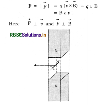
Net positive and negative charges will accumulate at the ends of the wire creating an electric field that will cause a force on the electrons in a direction that is opposite to the direction of the Lorentz force. Clearly, when a certain amount of accumulation of charges has taken place such that the electric force and the magnetic Lorentz force cancel, there will be no further movement of the ‘free’ electrons. The two ends of the wire thus become like the two terminals of a battery without any external connection.
Let V = P.D or induced e.m.f. developed across the ends of the conductor
∴ Electric field,
E = \(\frac{\mathrm{V}}{\mathrm{l}} \)
Force on electron due to electric field
F' = eE = \(\frac{e \mathrm{~V}}{l}\)
But F' = F
\(\frac{e \mathrm{~V}}{l}\) = B e v
∴ V = B l v
This is the e.m.f. induced across the two ends of the conductor.
(ii) A closed loop moving completely in magnetic field. Fig. LAQ 5 (b) shows a closed rectangular loop PQRS of metallic wire held horizontally in a uniform magnetic field \(\vec{B}\) acting ⊥ to the plane of the loop.
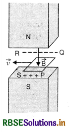
When the loop is dragged horizontally to the left with a velocity v, Lorentz force acts on the electrons in arms PQ and RS. Therefore, negative charges accumulate on QR and positive charges accumulate on PS, assuming that the loop is completely within the magnetic field. Though QR and PS are connected by conducting wires PQ and RS yet no flow is possible because a continuous path for the flow of electrons is not available, Fig. (b).
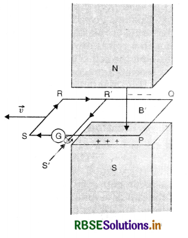
(iii) A closed loop moving partially in a magnetic field. Suppose a part PQR'S' is inside the magnetic field and portion R'S'SR is just outside the field. R'S' is another wire connecting QR and PS, Fig. 661 (c). The negative charges accumulated on R' and positive charges accumulated on PS find a conducting path S'SRR’S’ for their continuous flow. Therefore, current begins to flow in this loop as is indicated by galvanometer G. This is the induced current.

Question 12.
What are eddy currents? How are these produced? In what sense are the eddy currents considered undesirable in transformer and how are these reduce in such devices?
Answer:
Eddy current. When a solid conductor moves across a magnetic field or is placed in a changing magnetic field, the flux linked with the conductor changes and, therefore, induced (circulating) currents are set up in the conductor. In accordance with Lenz’s law, the direction of the induced currents opposes the motion of the conductor or the charges in the field to which they are due. Such circulating currents are called Focault's currents or eddy currents. Since the resistance of metal piece is quite low, these currents may be quite large and may produce heating or damping effects. Fig. LAQ 8 (a).
Thus eddy currents are the current induced in a conductor, when placed in changing magnetic field.
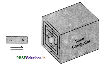
Magnitude of eddy current
I = \(\frac{\text { Induced e.m.f }(e)}{\text { Resitance }(\mathrm{R})}=\frac{e}{\mathrm{R}}\)
Since e = \(-\frac{d \phi}{d t}\)
∴ I = \(-\frac{d \phi / d t}{\mathrm{R}}=-\frac{1}{\mathrm{R}} \frac{d \phi}{d t}\)
The direction of I is given by Lenz’s law or Fleming’s right hand rule.
Note. Fleming’s Right Hand Rule
It states that if we stretch the first finger, central finger and thumb of our right hand in mutually perpendicular directions such that the first finger points along the direction of magnetic field and the thumb along the direction of motion of the conductor, tfien central finger would gives us the direction of induced e.m.f.
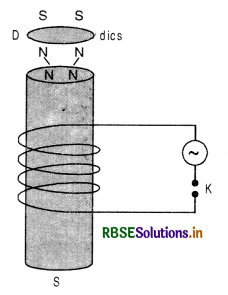
Illustrations
(i) If a light metallic disc D is placed at top of an electromagnet as shown in Fig. LAQ 8 (b) and a.c. is passed through the coil, the disc is thrown up due to eddy currents.
Explanation. On passing the current in the coil, the magnetic flux linked with the coil starts growing and thus magnetic flux linked with the solenoid and hence with the disc also increases and induced current is produced in the disc which converts it into a small magnet. The upper end of the iron core and lower face of the disc acquire the same polarity in accordance with Lenz’s law and due to repulsion between the upper end of soft iron and lower face of disc D, the disc is thrown up.
(ii) A simple pendulum is made of sheet of copper as shown in Fig. LAQ 8 (c). It is made to oscillate between the pole piece of an electromagnet. When the magnetic field is off, the metal plate oscillates freely for a long time. But when the magnetic field is switched on, the motion of the plate is damped due to production of eddy currents, because when the metal plate is displaced towards any one extreme position the area of the plate in the field decreases and magnetic flux linked with the plate decreases and eddy currents are produced which opposes the motion of the plate and thus produces damping. If the strength of magnetic field is very high, the plate is unable to move in the magnetic field and its motion becomes dead beat.
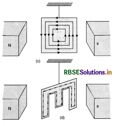
If the same experiment is repeated by a slotted plate Fig. LAQ 8 (d) the motion of plate is not much affected by the magnetic field because eddy currents are reduced as the same closed loop has a much longer path as shown by dotted closed line in Fig.(d). Longer path means more resistance, hence eddy currents will be reduced.
In a transformer the changing magnetic flux produces eddy currents in the iron core of the transformer and leads to the wastage of energy in the form of heat. This wastage of energy can be minimised by using a laminated iron core.
To minimize the eddy currents
To minimize the heating and breaking effect of eddy currents, the desired iron or metal frame to be used in the appliance is taken in the form of thin sheets, each one of which is electrically insulated from the other. Further the sheets are so adjusted that their planes are perpendicular to the direction of currents which would be set up by the emf induced in the metal. As the insulation layers between the sheets offer large resistance and the area of the conductor is reduced, the eddy currents are thus reduced.
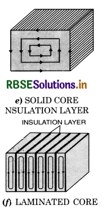
Application of eddy currents. Eddy currents have been put to the following important uses:
1. Speedometers. In a speedometer, a drum rotates according to the speed of the vehicle. The magnet is placed inside an aluminium drum which is carefully pivoted. When the magnet swings, it drags the drum also through a certain angle depending upon the speed of the vehicle.
2. Induction furnace. A metallic substance which is to be melted is placed in a high frequency magnetic field. Large eddy currents will be produced in the substance and so much heat is produced that it melts the substance. This arrangement is used to separate metal from its ore and some alloys of metal can be formed.
3. Dead beat Galvanometer. When steady (constant) current is passed through the coil of a galvanometer, it is deflected and oscillates about its equilibrium position for a long time. But if the same coil is wound over a metallic frame and as current is passed in the coil, eddy currents are produced in the metal frame which opposes the motion of the coil and makes it dead beat i.e. non-oscillatory. This is also called electromagnetic damping.
4. Damping. To stop the vibrations of ballistic galvanometer, the galvanometer is shunted by connecting external shunt resistance across whole of the coil. Smaller the shunt, greater are the eddy currents. The eddy currents thus damp the motion of ballistic galvanometers.
5. Induction motor. In an a.c. induction motor, a metallic cylinder is placed in the rotating magnetic field. Eddy currents are produced in the cylinder which try to decrease the relative motion between rotating magnetic field and the cylinder. As a result, the cylinder also starts rotating about its axis.
6. Magnetic brakes. When a train moves, the axis of the wheel also rotates. A drum attached to the axle also starts rotating. Whenever the train is required to be stopped, a magnetic field is applied to the rotating drum. The eddy current production in the drum apply upon it an opposing torque and as a result the train stops immediately.

Question 13.
Define mutual inductance between a pair of coils. Derive an expression for the mutual inductance of two long coaxial solenoids of same length wound over the other.
Answer:
Mutual induction. The phenomenon of producing an induced current in a coil or circuit by changing current in a neighbouring circuit, is called mutual induction.
Illustration
Consider two coils P1P2 and S1S2 placed close to each other. Coil P1P2 connected to battery and key k are called primary coils.
The coils S1S2 connected to galvanometer are called secondary coils.
When key k is inserted, the current starts increasing from zero to maximum. The magnetic flux linked to P1P2 also increases from zero to maximum. The magnetic flux passing through S1S2 also changes producing induced current in secondary.
According to Lenz’s law, the direction of current in the secondary coil at the time of make is in a direction opposite to battery current in the primary.
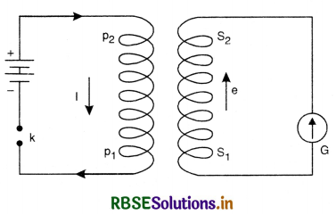
As the key is removed, the current in the primary decreases from maximum to zero, the magnetic flux linked with primary and hence with secondary also decreases from maximum to zero. The induced current will again be set up in the circuit the direction of which will be the same as that of battery current at the time of make.
Mutual Inductance of two solenoids
Consider two large solenoids A and B each of the length l such that solenoid A surrounds B.
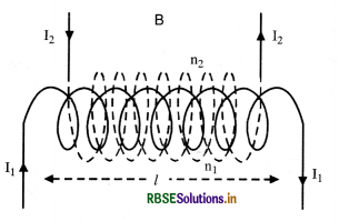
Let n1 = No. of turns per unit length of A
I1 = strength of current in A.
n2 = No. of turns per unit length of B.
I2 = strength of current in B
The axes of two solenoids are kept parallel.
It is assumed that magnetic field produced inside the solenoid is uniform and outside it, is zero.
Magnetic flux linked with inner solenoid due to current in outer solenoid is
Φ2 = µ0 x Magnetic field x Area x No. of turns
or Φ2 = µ0 n1 I1 x a x n2 I.
Comparing with equation
Φ2 = MBA I1
where MBA = coefficient of mutual induction of B when current is through A
MBA = µ0 n1 n2 la ...........................(1)
Now consider flux linked with outer solenoid A due to I2
The magnetic field due to I2 is constant inside the inner solenoid B but zero in the annular region between two solenoids.
∴ Φ1 = µ0 n1 I2 an2 l
Again Φ1 = MAB I2
∴ MAB = µ0 n1 n2 la .................................(2)
Comparing (1) and (2),
MBA = MAB = M (say)
Hence, coefficient of mutual induction between two long solenoids,
M = µ0 n1 n2 la.
HOTS QUESTIONS
Question 1.
The magnetic flux passing perpendicular to the plane of the the coil and directed into the paper is varying according to the relation Φ = 6t2 + 7t + 1.
Where Φ is in milliweber and t is in seconds.
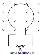
(i) What is the magnitude of e.m.f. induced in the loop when t = 2s?
(ii) What is the direction of current through resistor R?
Answer:
(i) Induced e.m.f.
e = \(\frac{d \phi}{d t}\) (in magnitude)
= \(\frac{d}{d t}\)(6t2 + 7t + 1) x 10-3
= (12t + 7) x 10-3 volt
At t = 2, e = 12 x 2 + 7 x 10-3 = 31 mV.
(ii) The current in the loop will tend to produce magnetic field in a direction opposite to the given magnetic field (i.e. for upward direction), the current induced in the loop be in anticlockwise direction. So the current in resistor R will be from left to right.

Question 2.
A copper rod of length 0.18 m is moving with a uniform velocity 10 ms-1 parallel to a long straight wire carrying a current of 5.0 A. The rod itself is perpendicular to the wire with its ends at distances 0.01 m and 0.2 m from it. Calculate the e.m.f. induced in the rod.
Answer:
Let the given rod be made up of large number of elements. Let us consider one such element of length dx at a distance x from the wire as shown in the figure.
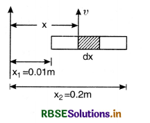
Magnetic field due to the wire carrying current at a distance x is given by.
B = \(\frac{\mu_0}{2 \pi} \frac{\mathrm{I}}{x}\)
E.m.f. induced in the element dx
de = Bvdx = \(\frac{\mu_0}{2 \pi} \frac{\mathrm{I}}{x} vdx\)
Total induced e.m.f. in the rod
e = \(\int d e=\frac{\mu_0 \mathrm{I} v}{2 \pi} \int_{x_1}^{x_2} \frac{1}{x} d x\)
= \(\frac{\mu_0 \mathrm{I} v}{2 \pi} \ln \frac{x_2}{x_1}\)
= \(\frac{4 \pi \times 10^{-7} \times 5 \times 10}{2 \pi} \ln \frac{0.2}{0.01}\) = 10-5 ln 20
= 10-5 x 2.3026 log1020 = 10-5 x 2.3026 x 1.3010
= 2.996 x 10-5 = 30 µV.
Question 3.
A long solenoid of length 1 m, cross sectional area 10 cm2, having 1000 turns has wound about its centre a small coil of 20 turns. Compute the mutual inductance of the two circuits. What is the e.m.f. in the coil when the current in the solenoid changes at the rate of 10As-1?
Answer:
Magnetic field at the centre of solenoid
B1 = \(\frac{\mu_0 \mathrm{~N}_1 \mathrm{I}_1}{l}\) ............................(i)
The flux linked with the coil of N2 turns wound at the centre of solenoid.
Φ2 = N2B1A2
Using eqn. (i), we get
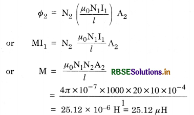
Magnitude of induced e.m.f.
e = M\(\frac{d \mathrm{I}}{d t}\) = 25.12 x 10-6 x 10 = 251.2 x 10⁻⁶ V
= 251.2 µV
Question 4.
An air core solenoid of 80 cm length has 500 turns and its circular cross-section has a diameter of 2 cm, calculate
(i) the self inductance of the solnoid
(ii) the self linked flux when the current in the solenoid is 2A.
(iii) the rate of change of current in the solenoid that will produce a self induced e.m.f. of 0.3 V.
Answer:
(i) Self inductance of the solenoid
L = \(\frac{\mu_0 \mathrm{~N}^2 \mathrm{~A}}{l}=\frac{\mu_0 \mathrm{~N}^2 \pi r^2}{l}\)
Given N = 500, r = \(\frac{\mathrm{D}}{2}=\frac{2}{2}\) = 1 cm = 10-2 m, l = 80 cm = 0.8 m
So L = \(\frac{4 \pi \times 10^{-7} \times(500)^2 \times \pi \times\left(10^{-2}\right)^2}{0.8} \)
= 123.2 x 10⁻⁶H
(ii) Effective flux = LI = 123.2 x 10-6 x 2
= 246.4 x 10⁻⁶ Wb
Flux linked per turn = \(\frac{246.4 \times 10^{-6}}{500}\) = 0.49 x 10⁻⁶ Wb
(iii) Since e = L\(\frac{d \mathrm{I}}{d t}\) (in magnitude)
\(\frac{d \mathrm{I}}{d t}=\frac{e}{\mathrm{~L}}=\frac{0.3}{123.2 \times 10^{-6}}\) = 2.43 x 10³ As-1.

Question 5.
A current I = 3.36 (1 + 2t) x 10-2A increases at a steady rate in a long straight wire. A small circular loop of radius 10-3 m has its plane parallel to the wire and is at a placed at a distance of 1 m from the wire. The resistance of the loop is 8.4 x 10⁴ Ω. Find the magnitude and the direction of the induced current in the loop.
Answer:
Given I = 3.36 (1 + 2t) x 10-2 A, r = 1 m, x = 10-3 m
Magnetic field at the centre of the loop due to current in the wire.
B = \(\frac{\mu_0 \mathrm{I}}{2 \pi r}\) (⊥ to the plane of loop)
Magnetic flux linked with the loop
Φ = BA cos 0° = BA = B x πr2
