RBSE Class 12 Physics Important Questions Chapter 10 Wave Optics
Rajasthan Board RBSE Class 12 Physics Important Questions Chapter 10 Wave Optics Important Questions and Answers.
RBSE Class 12 Physics Chapter 10 Important Questions Wave Optics
Multiple Choice Questions
Question 1.
Light travels faster in air than in glass according to:
(A) wave theory of light
(B) corpuscular theory of light
(C) Both (A) and (B)
(D) Neither (A) nor (B).
Answer:
(A) wave theory of light

Question 2.
Which of the following undergo maximum diffraction?
(A) α-rays
(B) γ-rays
(C) Radio waves
(D) Light waves.
Answer:
(C) Radio waves
Question 3.
Which of the following does not support the wave nature of light?
(A) Interference
(B) Diffraction
(C) Polarisation
(D) Photoelectric effect.
Answer:
(D) Photoelectric effect.
Question 4.
Ratio of intensity of two waves is given by 4 : 1. Then, ratio of the amplitude of the two waves is:
(A) 2 : 1
(B) 1 : 2
(C) 4 : 1
(D) 1 : 4.
Answer:
(A) 2 : 1
Question 5.
One cannot see through fog, because:
(A) fog absorbs the light
(B) light suffer total reflection at droplets
(C) refractive index of the fog is infinity
(D) light is scattered by droplets.
Answer:
(D) light is scattered by droplets.
Question 6.
Two waves of intensities I and 4 I superimpose, then maximum and minimum intensities are:
(A) 5 I and 3 I
(B) 9 I and I
(C) 9 I and 3 I
(D) 5 I and I.
Answer:
(B) 9 I and I

Question 7.
According to Huygen’s principle, light is a form of:
(A) particle
(B) wave
(C) rays
(D) none of these.
Answer:
(B) wave
Question 8.
Huygen’s wave theory of light could not explain:
(A) diffraction
(B) photoelectric effect
(C) polarisation
(D) interference.
Answer:
(B) photoelectric effect
Question 9.
Bending of light into regions of geometrical shadow is called:
(A) polarisation
(B) interference
(C) diffraction
(D) refraction.
Answer:
(C) diffraction
Question 10.
The resolving limit of healthy eye is about
(A) 1'
(B) 1''
(C) 1°
(D) \(\frac{1}{60}{ }^{\prime \prime}\).
Answer:
(A) 1'
Question 11.
Polarised light can be produced by:
(A) dispersion
(B) scattering
(C) interference
(D) diffraction.
Answer:
(B) scattering
Question 12.
Light waves are transverse, because they:
(A) get reflected
(B) get polarised
(C) get diffracted
(D) do not get polarised.
Answer:
(B) get polarised
Question 13.
The waves that cannot be polarised are:
(A) Longitudinal
(B) Transverse
(C) Electromagnetic
(D) Light.
Answer:
(A) Longitudinal
Question 14.
The shape of wave front emitted by a light source in the form of a narrow slit is:
(A) cylinderical
(B) spherical
(C) plane
(D) None of the above.
Answer:
(A) cylinderical

Question 15.
The phase difference between any two points situated on the same wavefront is:
(A) 2π
(B) π
(C) \(\frac{\pi}{2}\)
(D) zero.
Answer:
(D) zero.
Question 16.
Which of the following phenomena is not common to sound and light waves?
(A) Interference
(B) Diffraction
(C) Polarisation
(D) Reflection.
Answer:
(C) Polarisation
Question 17.
How are resolving power (RP) and limit of resolution (LR) of an optical instrument related?
(A) LR = RP
(B) RP = \(\frac{1}{\mathrm{LR}}\)
(C) RP = LR2
(D) None.
Answer:
(B) RP = \(\frac{1}{\mathrm{LR}}\)
Question 18.
What is the critical angle for material of refractive index \(\sqrt{2}\)?
(A) 0°
(B) 30°
(C) 45°
(D) 90°.
Answer:
(C) 45°
Fill in the blanks
Question 1.
The sources of light should be preferably .............................. for interference.
Answer:
monohromatic.
Question 2.
For constructive interference, path difference = ..............................
Answer:
\(\frac{n \lambda \mathrm{D}}{d}\).
Question 3.
.............................. are materials used to polarise light.
Answer:
Polaroids.

Question 4.
The speed of light in glass having refractive index of 1.5 = .............................. ms-1.
Answer:
2 x 10⁸.
Question 5.
Radius of curvature of plane wavefront is ..............................
Answer:
infinity.
Question 6.
Two independent sources .............................. produce interference.
Answer:
cannot.
Question 7.
The width of dark and bright fringes are ..............................
Answer:
equal.
Question 8.
Diffraction maxima are .............................. uniformly bright.
Answer:
not.
Question 9.
Blue colour of the sky is due to the .............................. of light.
Answer:
scattering.

Question 10.
Only .............................. wave can be polarized.
Answer:
transverse.
Very Short Answer Type Questions
Question 1.
Define wavefront.
Answer:
The locus of the particles of the medium in the same vibrating phase, is called wavefront.
Question 2.
Name different types of wavefronts.
Answer:
The different types of wavefronts are circular, spherical, plane and cylindrical.
Question 3.
Define a ray.
Answer:
Normals drawn on wavefront, called ray.
Question 4.
Give nature of rays associated with different types of wavefronts.
Answer:
Spherical'wavefront gives diverging rays. Plane wavefront gives parallel rays.
Question 5.
Name the constant ratio of the sine of angle of incidence to the sine of angle of refraction.
Answer:
The ratio is called refractive index of the refracting medium.
Question 6.
Which coherent sources produce fine interference?
Answer:
Narrow and close coherent sources produce fine interference.
Question 7.
What are coherent sources of light?
Answer:
Coherent sources are those sources which emit continuously the waves of the same wavelength and amplitude either in the same phase or with a constant phase difference. This is possible if two sources are obtained out of a single source.

Question 8.
In which case interference is produced?
Answer:
Interference is produced when the two superimposing waves have the same frequencies and stable phase difference between them.
Question 9.
In which case no interference is produced?
Answer:
Interference is not produced wThen the two superimposing waves have different frequencies.
Question 10.
State the essential conditions for the two light waves to be coherent.
Answer:
- Two sources should give monochromatic light.
- Coherent sources should be obtained from a single source so that the change in phase in one source is simultaneously accompanied by the same change in other.
- Path difference between the two waves should be small.
Question 11.
What is the main condition to produce interference of light?
Answer:
The two sources producing interference must be coherent sources.
Question 12.
What is Huygens’ principle?
Answer:
Huygens’ principle is, infact, a geometrical construction which is used to determine the position of a wavefront at a later time from its position at any instant. It supposes that every point on the primary wavefront is a source of secondary wavelets.
Question 13.
What becomes of the energy of light waves in destructive interference?
Answer:
Energy of light is transferred to the region where the intensity is further increased.
Question 14.
Can we get interference using white light?
Answer:
Yes, the fringes will be coloured.
Question 15.
Give the shape of interference rings observed in a Young’s double slit experiment.
Answer:
We get straight dark and bright lines parallel to the slits.
Question 16.
When is the interference constructive?
Answer:
Interference is constructive when phase difference is
2πn (n = 0, 1, 2, 3,.........................)

Question 17.
When is the interference destructive?
Answer:
Interference is destructive when phase difference is
(2n + 1) π (n = 0, 1, 2, 3,....................)
Question 18.
Write interference term associated with superposition of two electromagnetic waves.
Answer:
The required term is, 2k \(\left(\overrightarrow{\mathrm{E}}_1 \cdot \overrightarrow{\mathrm{E}}_2\right)\).
Question 19.
When is interference term zero?
Answer:
Interference term is zero when \(\overrightarrow{\mathrm{E}}_1\) and \(\overrightarrow{\mathrm{E}}_2\) are perpendicular to each other.
Question 20.
In Young’s double slit experiment what is the shape of interference fringes?
Answer:
Nearly straight lines in shape.
Question 21.
What happens to the interference pattern if two coherent sources in Young’s experiment are infinitesimally close to one another?
Answer:
Interference pattern will not be observed because as the two sources merge and becomes a single source of light.
Question 22.
Why do the oil films on the surface of water appear to be coloured?
Answer:
Due to interference of white light reflected time and again (multiple reflection) from the upper surface and lower surface of the oil film, we see colours.
Question 23.
When a low flying aircraft passes over our head, we sometimes note slight shaking of the picture on our TV screen. Suggest a possible explanation.
Answer:
Interference of direct signal received from the antenna with the (weak) signal reflected by the passing aircraft causes shaking of the picture on our T.V. screen.
Question 24.
What is diffraction of light?
Answer:
The phenomenon of bending of light round the sharp corners and spreading into region of the geometrical shadow is called diffraction of light.
Question 25.
Is it correct to say that diffraction is interference between different parts of the same wavefront?
Answer:
Yes.
Question 26.
Do longitudinal or transverse waves show diffraction?
Answer:
Both.
Question 27.
What is the ratio of velocity of light of wavelengths 4000 Å and 8000 Å in vacuum?
Answer:
The ratio is 1 : 1 because velocity of light is independent of wavelength.

Question 28.
At what angle of incidence should light beam strike a glass slab of refractive index (µ = \(\sqrt{3}\)), such that the reflected and refracted rays are perpendicular to each other?
Answer:
Since
tan ip = µ
So tan ip = \(\sqrt{3}\)
or ip = 60°
Question 29.
Name two commonly used devices which use polarised light.
Answer:
Sun glasses (dark glasses) and liquid crystal display (LCD).
Question 30.
Does the value of polarizing angle depend on colour of light?
Answer:
Yes, it depends.
Question 31.
Draw a graph showing the variation of intensity of polarized light transmitted by an analyser.
Answer:
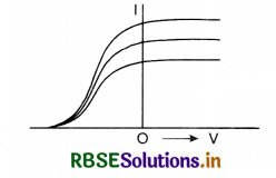
Question 32.
Why can we not get diffraction from a wide slit illuminated by a monochromatic light?
Answer:
As the half period of elements contained in a wide slit are very large so the resultant effect is a general illumination.
Question 33.
Can electromagnetic waves be polarised?
Answer:
Yes.
Question 34.
Does the value of wavelength of light have any role in polarisation?
Answer:
No. The electromagnetic waves of all wavelengths can be polarised.
Question 35.
Does the value of polarising angle depend on colour of light?
Answer:
Yes. Because tan ip = µ, and colour of light depends upon the wavelength and wavelength depends upon µ.

Question 36.
What information do we get about the nature of light by polarisation?
Answer:
Polarisation is possible only in transverse wave motion. So polarisation of light means light is transverse in nature.
Question 37.
Can our eye distinguish polarised light from unpolarised light?
Answer:
No, naked eye cannot distinguish polarised light from unpolarised light.
Question 38.
Define polarisation.
Answer:
The phenomenon due to which the transverse vibrations of electric field vector of a light wave become confined to one plane, is called polarisation.
Question 39.
What is function of first crystal?
Answer:
First crystal polarises light. It is called poiariser.
Question 40.
What is function of second crystal?
Answer:
Second crystal analyses light. It is called analyser.
Question 41.
Why central maxima is white with white light?
Answer:
For central maxima y = 0, n = 0 for all values of λ. Hence all coloured waves reach O in the same phase and make central maxima white.
Question 42.
The polaroids are placed at 90° to each other and the transmitted intensity is zero. What happens when one of them is rotated?
Answer:
The intensity of light transmitted from the second polaroid increases from zero and will become maximum when the two polaroids are parallel to each other.
Question 43.
How does the fringe width of interference fringe change, when the whole apparatus of Young’s experiment is kept in a liquid of refractive index 1.3?
Answer:
In the 1st case
Fringe width ß = \(\frac{\lambda \mathrm{D}}{d}\)
In second case,
When its apparatus is immersed in a liquid of refractive index µ = 1.3.
The wavelength becomes λ' = \(\frac{\lambda}{\mu}\)
So ß' = \(\frac{\beta}{\mu}=\frac{\beta}{1.3}\)
i.e. Fringe width decreases to \(\frac{1}{1.3}\) times.
Question 44.
How does the angular separation of interference fringes change in Young’s experiment, if the distance between the slits is increased?
Answer:
Angular separation, \(\frac{\beta}{\mathrm{D}}=\frac{\lambda}{d}\)
So, if d is decreased, then angular separation will decrease.
Question 45.
State with reason, why two independent sources of light cannot be considered on coherent sources.
Answer:
Because independent sources do not have a constant plase difference.
Question 46.
What is the geometrical shape of the wavefront when a plane passes through a convex lens?
Answer:
Converging spherical wavefront.

Question 47.
A parallel beam of monochromatic light falls normally on a single narrow slit. How does the angular width of the principal maxima in the resulting diffraction pattern depend on width of the slit?
Answer:
The angular width of principal maxima ∝ \(\frac{1}{a}\).
Question 48.
A parallel beam of monochromatic light falls normally on a single narrow slit. How does angular width of the central maximum in the resulting diffraction pattern depend on the wavelength of the incident light?
Answer:
Angular width of principal maxima ∝ λ.
Question 49.
How would the angular separation of interference fringes in Young’s double slit experiment change when the distance of separation between the slits and the screen is doubled?
Answer:
No change.
Because angular separation = \(\frac{\lambda}{d}\)
So it is independent of D.
Question 50.
A partially plane polarised beam of light is passed through a polaroid. Show graphically the variation of the transmitted light intensity with angle of rotation of the Polaroid.
Answer:
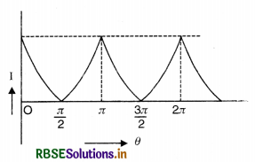
Question 51.
What are coherent sources of light?
Answer:
Coherent sources are those sources which emit continuously the waves of the same wavelength and amplitude either in the same phase or with a constant phase difference. This is possible if two sources are obtained out of a single source.
Question 52.
The polarising angle of a medium is 60°. What is refractive index of the medium?
Answer:
Since µ = tan ip = tan 60°.
So µ = \(\sqrt{3}\) = 1.732.
Question 53.
When the light undergoes refraction, what happens to its frequency.
Answer:
Frequency of light does not change in refraction.
Question 54.
State two conditions to obtain sustained interference.
Answer:
- The two light waves should be of the same frequency or wavelength.
- The two light waves should be in the same phase or should have a constant phase difference.
Question 55.
Why interference pattern not detected when two coherent sources are far apart.
Answer:
Fringe width ß = \(\frac{\lambda \mathrm{D}}{d}\). As the distance between two sources (d) is increased, ß decreases and when the sources are far apart, the fringe width becomes practically zero and the fringe pattern is not detected.
Question 56.
Sketch the variation of intensity of the interference pattern in Young’s double slit experiment.
Answer:
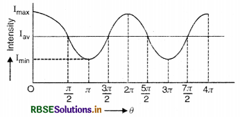
Question 57.
State the essential condition for diffraction of light to take place.
Answer:
The condition for diffraction of light to take place is that the size of obstacle or aperture should be comparable to the wavelength of incident light.
Question 58.
What is plane polarised light.
Answer:
Plane polarised light may be defined as the light, in which the vibrations of the light (electric vector) are restricted to a particular plane.
Question 59.
The refractive index of a material is \(\sqrt{3}\). What is the angle of refraction if the unpolarised light is incident on it at the polarising angle of the medium.
Answer:
Given µ = \(\sqrt{3}\), r = ?, i = ip
Since µ = tan ip
∴ ip = tan-1 (µ) = tan-1 \(\sqrt{3}\) = 60°
Also ip + r = 90°
∴ r = 90° - ip = 90° - 60° = 30°.

Question 60.
What is the speed of light in a denser medium of polarising angle 30°?
Answer:
Given ip = 30°, n = c/v = tan ip
Or n = \(\frac{c}{v}\) = tan ip ⇒ v = \(\frac{c}{\tan i_p} \)
v = \(\frac{3 \times 10^8}{\tan 30^{\circ}}\) = 3\(\sqrt{3}\) x 108 ms-1
Short Answer Type Questions
Question 1.
What are two assumptions on which Huygens’ principle is based? Explain Huygens’ geometrical construction for the wavefronts.
Answer:
Assumptions on which Huygens’ principle is based are:
- The medium is homogeneous.
- The medium is isotropic.
Huygens’ principle
(a) Each point of a wavelength becomes a source of new disturbance called the secondary wavelets which travel in all directions with the same speed provided the medium remains the same.
(b) The secondary wavefront is the tangent plane joining all the wavefronts.
Fig. SAQ 1 (a) represents the trace of secondary wavefront at a certain instant and Fig. SAQ 1 (b) represents the trace when the light has travelled a large distance.
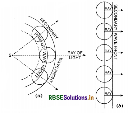
Rays of light are perpendicular to the wavefront.
Question 2.
Why are two bulbs lighting the same wall considered as incoherent sources? How do their intensities add up?
Answer:
The bulbs are incoherent sources because at any frequency, the radiation from one has no stable phase relation with the other. This is because independent atoms and electrons are responsible for the radiation for each source.
For two different frequencies, the interference term becomes zero
∴ the intensities of two bulbs get added up.
i.e., I = I1 + I2.
Question 3.
In Young’s double slit experiment, the separation of slits is doubled and the distance of the slits and screen is halved. How will it affect the fringe width?
Answer:
In interference pattern, the fringe width ß is given by
ß = \(\frac{\lambda \mathrm{D}}{d}\) .........................(1)
Let ß' be new fringe width, when d' = 2d and D' = \(\frac{\mathrm{D}}{2}\)
∴ ß' = \(\frac{\lambda \mathrm{D}^{\prime}}{d^{\prime}}=\frac{\lambda \mathrm{D}}{2.2 d}=\frac{\lambda \mathrm{D}}{4 d}\)
Using Eq. (1), we get
ß' = \(\frac{\beta}{4}\)
So the fringe width is reduced to one-fourth of its previous value.
Question 4.
What will happen if Young’s double slit experiment is performed in water?
Answer:
On immersing Young’s double slit apparatus in water having refractive index µ, then the wavelength of light λ becomes
λ' = \(\frac{\lambda}{\mu}\)
Since, fringe width ß in air
ß = \(\frac{\lambda \mathrm{D}}{d}\)
So in water, the fringe width ß' will be
ß' = \(\frac{\lambda^{\prime} \mathrm{D}}{d}=\frac{\lambda \mathrm{D}}{\mu d}=\frac{\beta}{\mu}\)
i.e. the fringe will decrease by a factor \(\frac{1}{\mu}\).

Question 5.
Can white light produce interference? What is its nature?
Answer:
Yes, white light can produce interference. In this case, the central, fringe will be white and first few coloured fringes will be formed and then the fringes of different colours overlap to produce general illumination, white in colour.
Question 6.
Width of two slits in Young’s experiment are in ratio of 1 : 4. What is the ratio of intensities of light wave from them?
Answer:
We know that the width of a slit is directly proportional to the square of amplitude of light (i.e. electric vector).
If W1 and W2 are the width of slits and ‘a1’ and ‘a2' are their respective amplitude of light waves, then W1 ∝ a12 and W2 ∝ a22
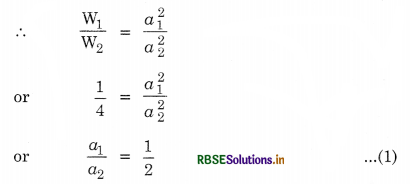
If Imax and Imin are maximum and minimum values of intensities of light, then
\(\frac{\mathrm{I}_{\max }}{\mathrm{I}_{\min }}=\frac{\left(a_1+a_2\right)^2}{\left(a_1-a_2\right)^2}=\frac{\left(\frac{a_1}{a_2}+1\right)^2}{\left(\frac{a_1}{a_2}-1\right)^2}\)
or \(\frac{I_{\max }}{I_{\min }}=\frac{\left(\frac{1}{2}+1\right)^2}{\left(\frac{1}{2}-1\right)^2}=\frac{9}{1}=9\)
Question 7.
What is the ratio of slit widths, when amplitude of light wave from them have a ratio \(\sqrt{2}\)/1?
Answer:
If W1 and W2 are the widths of slits and a1 and a2 respectively, the amplitude of light waves, then, we have
\(\frac{\mathrm{W}_1}{\mathrm{~W}_2}=\frac{a_1^2}{a_2^2}=\left(\frac{a_1}{a_2}\right)^2=\left(\frac{\sqrt{2}}{1}\right)^2\)
= \(\frac{2}{1}\)
Question 8.
Two polaroids are placed at 90° to each other and the intensity of transmitted light is zero. What will be the intensity of transmitted light, when one or more polaroids is placed between these two bisecting the angle between them? Take intensity of unpolarised light as I0.
Answer:
The polaroid is placed bisecting the angle of 90° i.e. at 45°.
So intensity of emitted light is
I = I0 cos 45° = \(\frac{\mathrm{I}_0}{\sqrt{2}}\)
= 0.707 I0.
Question 9.
Doppler’s effect in sound is different depending on whether the source or observer is in motion. However, in case of light, the Doppler’s shift is the same irrespective of whether the source or observer is in motion, explain how?
Answer:
The velocity of sound is comparable to velocity of source or observer, hence the velocity of sound depends on the motion of source or observer. But the velocity of light is very large as compared to the velocity of source or observer and in free space (or air) is independent of velocity of source or observer. Hence Doppler’s shift is the same irrespective of whether the source or observer is in motion.

Question 10.
A double slit is illuminated by light of wavelengths 6000 Å. The slits are 0.1 cm apart and screen is placed 1.5 m. away. Calculate the angular position of 9th maximum in radian.
Answer:
λ = 6000 Å = 6 x 10⁻⁷ m, d = 0.1 cm = 10-3 m, D = 1.5 m, n = 9
Angular position of nth maximum
θn = \(\frac{y_n}{\mathrm{D}}=\frac{\frac{n \lambda \mathrm{D}}{d}}{\mathrm{D}}=\frac{n \lambda}{d}\)
or θn = \(\frac{9 \times 6 \times 10^{-7}}{10^{-3}}\)
= 54 x 10-4
= 0.0054 radian.
Question 11.
What should be the amplitude of the interfering beams to produce a completely dark fringe? Why?
Answer:
To produce a completely dark fringe the amplitude of the interfering beams should be equal because at destructive interference (i.e. for dark fringe) the amplitude of two beams is equal to the difference of the amplitudes of two superimposing waves. Thus for complete darkness, the amplitude must be zero. This is possible only when the amplitude of two beams are equal in magnitude.
Question 12.
The medium in which the Young’s double slit experiment is set up, is replaced by an optically denser medium. How will the interference pattern vary? Explain.
Answer:
The fringe width is given by
ß = \(\frac{\lambda \mathrm{D}}{d}\)
or ß ∝ λ
When the medium is replaced by an optically denser medium, the velocity of light decreases, and hence the wavelength λ (= c) also decreases (v remains constant). Hence the fringe width will decrease.
Question 13.
Show that maximum intensity in interference pattern is four times the intensity due to each slit. Hence show that interference involves only redistribution of energy.
Answer:
Let 'a' be amplitude of waves from each slit, hence, a2 is the intensity due to each slit
∴ Before interference,
Average intensity = a2 + a2 = 2a2
So maximum intensity
= (a + a)2 = (2a)2 = 4a2
i.e. maximum intensity is four times the intensity due to each slit.
And minimum intensity = (a - a)2 = 0
Also average intensity in interference pattern
= \(\frac{0+4 a^2}{2}\) = 2a2
= Average intensity before interference.
Hence the interference involves only redistribution of energy keeping the total energy constant.
Question 14.
What happens to fringe width, when the separation between the slits as well as distance of the screen from the slit are halved?
Answer:
Since fringe width,
ß = \(\frac{\lambda \mathrm{D}}{d}\)
When D' = \(\frac{\mathrm{D}}{2}\) and d' = \(\frac{d}{2}\), then
The new fringe width,
ß' = \(\frac{\lambda \mathrm{D}^{\prime}}{d^{\prime}}=\frac{\lambda \mathrm{D}}{2} \times \frac{2}{d}\)
= \(\frac{\lambda \mathrm{D}}{d}\) = ß
i.e. the fringe width remains the same.
Question 15.
Why two independent sources cannot produce sustained interference?
Answer:
The two independent sources cannot act as coherent sources because the phase difference changes 108 times in one second and due to this fast variation of phase, the position of maxima and minima also varies, so the interference pattern is produced but undetected i.e. the two independent sources cannot produce sustained interference.
Question 16.
Light from two coherent sources is reaching the screen. If the path difference at a point on the screen for the yellow light be \(\frac{3 \lambda}{2}\), then what will be the colour of the fringe at that point?
Answer:
If the light is white, the fringes will be coloured, however, the yellow and neighbouring colours shall be absent. If the source is emitting yellow light (i.e. monochromatic) there will be dark fringe at that point.
Question 17.
Why light can travel in vacuum whereas sound cannot do so?
Answer:
Light waves are electromagnetic waves and hence do not require any material medium for propagation hence light can travel in vacuum. The sound waves are mechanical waves and material medium is a must for them to travel, hence they cannot travel in vacuum.
Question 18.
What will be the effect on interference fringes obtained in Young’s double slit experiment if (i) one slit is covered (ii) a source of light of higher wavelength is used. (iii) distance between two slits be increased to 1 cm and (iv) distance between screen and double slit is increased.
Answer:
The fringe width ß is given by
ß = \(\frac{\lambda D}{d}\)
where λ is the wavelength of light incident, D is the distance between the screen and double slit and d is the distance between the two slits.
- On covering one slit, the interference pattern will be replaced by diffraction pattern due to single slit.
- On increasing the wavelength of incident light λ, the fringe width will increase.
- On increasing d by 1 cm, the fringe will disappear and there will be uniform illumination.
- On increasing D, the fringe width will increase.

Question 19.
The phase difference between the light waves emerging from the slits of the Young’s experiment is π radian. Will the central fringe will be dark or bright?
Answer:
The path difference between the waves reaching at the central fringe is zero, and if π radian is the initial phase difference between two waves, then the central fringe will be dark.
Question 20.
Can two electric bulbs of the same power and having filaments of the same material placed close to each other produce interference on the screen?
Answer:
No, the interference pattern will not be obtained on the screen because the two electric bulbs are not coherent sources and the path difference from two incoherent sources will change randomly. Thus sustained interference pattern will not be observed but there will be general illumination on the screen.
Question 21.
Why is the diffraction of sound more evident in daily life than light waves?
Answer:
It is because the wavelength of sound is much greater than that of light waves and is comparable with size of the obstacle wrhich is the essential condition for diffraction of waves.
Question 22.
Compare single slit diffraction pattern due to monochromatic light and white light.
Answer:
When source of light is monochromatic, the diffraction pattern consists of alternate bright and dark bands of unequal width. The central bright fringe has maximum intensity. The intensity of secondary maxima falls off rapidly.
When source is emitting white light, the diffraction pattern is coloured. The central maxima is white, but other bands are coloured. As band width ∝ λ, therefore, red band with higher wavelength is wider than the violet band with smaller wavelength.
Question 23.
A slit or an aperture diffracts light. Even then we say light travels in a straight line and ray optics is valid. Comment.
Answer:
A slit of width a diffracts a beam of light. Half angular width of central maximum is:
θ ≅ sin θ = \(\frac{\lambda}{a}\)
In travelling distance z, half angular width of beam would become \(\left(\frac{z \lambda}{a}\right)\)
This width will become more than width of slit, i.e. \(\frac{z \lambda}{a}\) > a, where z > \(\frac{a^2}{\lambda}\)
We call \(\frac{a^2}{\lambda}\) = zF, Fresnel distance.
Now, for a = 3 mm = 3 x 10⁻³ m
λ = 5000 Å = 5 x 10⁻⁷ m
zF = \(\frac{a^2}{\lambda}=\frac{\left(3 \times 10^{-3}\right)^2}{5 \times 10^{-7}}\) = 18 m
This means width of beam due to diffraction remains equal to the size of the width of the slit (3 x 10⁻³) i.e. diffraction effect can be neglected (upto 18 m) and ray optics is valid.
Question 24.
What is the condition regarding the size of the obstacle for observing the diffraction?
Answer:
The size of the obstacle should be of the same order as the wavelength of light.
Question 25.
Coloured spectrum is seen when we look through a muslin cloth. Why?
Answer:
Muslin cloth is made of very thin threads which act as slits. White light passing through these slits is diffracted giving rise to coloured spectrum.

Question 26.
Radio waves diffract pronoucedly around buildings, while light waves, which are electromagnetic waves, do not. Why?
Answer:
Since phenomenon of diffraction is observed only when size of the obstacle is comparable to the wavelength of the wave. The wavelength of radio waves (particularly short waves) have wavelength comparable to general objects like buildings and hence easily get diffracted. But wavelength of light is very small (3900 Å to 7800 Å). So they are not diffracted.
Question 27.
When a tiny circular obstacle is placed in the path of light from a distant source, a bright spot is seen at the centre of shadow of the obstacle. Explain.
Answer:
The light waves diffracted from the edges of the circular obstacle interfere destructively at the centre of the shadow producing bright spot at the centre of the shadow.
Question 28.
Two students are separated by a 7 m partition wall in a room 10 m high. If both light and sound waves can bend around the obstacle, how is that the students are unable to see each other even though they can converse easily?
Answer:
Since for diffraction to take place, the size of the obstacle or aperture should be comparable to the wavelength of incident wave. For sound, the frequency of sound v = 340 Hz (say), and its wavelength is λ = \(\frac{v}{y}=\frac{340}{340}\) = 1 m. is comparable to the size of the partition and for light the wavelength is of the order of 10-7 m. So sound can bend around the partition while light waves cannot.
Question 29.
What is difference between diffraction and interference?
Answer:
Differences between interference and diffraction.
- Interference is the result of superposition of light from two different wavefronts produced by two coherent sources whereas diffraction is the superposition of secondary waves emitted from various points of the same wavefront.
- Interference fringes are of the same intensity whereas intensity of diffraction fringes fall rapidly.
- Interference fringes are equally spaced whereas diffraction fringes are unequally spaced.
- Minimas of interference fringes are of zero intensity but in case of diffraction fringes, minimas are never perfectly dark.
Question 30.
Two nearby narrow slits are illuminated by a single monochromatic source. Name the pattern obtained on the screen. One of the slits is now covered. What is the name of the pattern now obtained on the screen? Write two differences between the patterns obtained in the two cases.
Answer:
When two nearby narrow slits are illuminated by a single monochromatic source of light, wre get interference fringes on the screen i.e., we have alternatively bright and dark bands.
When one of the slits is covered, we have no interference pattern but have a general illumination on the screen. However, there may be a little diffraction pattern at the edge due to Fraunhoffer’s diffraction.
Differences. In first case, interference bands are alternatively bright and dark bands. All bands are of equal brightness.
In second case diffraction pattern at the edges are not of uniform brightness.
Question 31.
Explain, polarisation affords a convincing evidence of transverse nature of light.
Answer:
The phenomenon of interference and diffraction establishes the wave nature of light. Both these phenomena are exhibited by both the types of wave motion i.e., longitudinal and transverse.
In transverse wave motion the vibrations of particles take place in a direction perpendicular to the direction of propagation of the wave. Hence the vibration in ordinary light are distributed symmetrically in all directions in a plane perpendicular to the direction of propagation. Such light is called unpolarised light.
Light waves which exhibit different properties in different directions are called polarised light waves. This can be demonstrated by using a pair of tourmaline crystals in the path of light waves.
Question 32.
Why electric vector in the electromagnetic waves determines the polarisation rather than the magnetic vector.
Answer:
Since our eye is more sensitive to electric vector than the magnetic vector, so the electric vector describes the polarisation as well as other phenomenon than the magnetic vector.
Question 33.
Describe two commonly used devices which use polarised light.
Answer:
The two commonly used devices using polarised light are:
1. Liquid crystal display (L.C.D.)
2. Sun glasses (dark glasses).
1. Liquid crystal display. They are found in many watches and calculators.
Liquid crystals have long molecules whose direction can be controlled by applying electric fields. This is used to modify the light produced by polariser to make its polarisation perpendicular to the axis of an analyser. The analyser cuts these lights and produces dark regions. These dark regions are controlled and are used to form numbers and letters.
2. Sun glasses (dark glasses). These have polaroids. Glare from sunlight reflection from water can be reduced, if the polaroids cut out horizontally polarised light.

Question 34.
Does the value of polarising angle for a transparent medium depend upon the wavelength of the light?
Answer:
Yes. Because polarising angle ip and refractive index µ of the material of transparent medium are related by the relation µ = tan ip
Question 35.
A polariser and analyser are so oriented that intensity of light transmitted is maximum. What fraction of maximum light is transmitted when analyser is rotated through an angle of 60°?
Answer:
From Malus law, we have
I = I0 cos2 θ
Here θ = 60°
∴ \(\frac{\mathrm{I}}{\mathrm{I}_0}\) = cos 60° = \(\left(\frac{1}{2}\right)^2\) = \(\left(\frac{1}{4}\right)\).
Question 36.
How is a wavefront defined? Using Huygens’ principle draw a figure showing the propagation of a plane wave refracting at a plane surface separating two media. Hence verify Snell’s law of refraction.
Answer:
Wavefront is the locus of all the points of the medium vibrating in the same phase.
Let XY be a plane refracting surface separating rarer medium I of refractive index µ1, from denser medium II of refractive index µ2 [µ2 > µ1], then
\(\frac{\mu_2}{\mu_1}=1 \mu_2=\frac{v_1}{v_2}\)
Where v1 is the velocity of light in medium I and v2 is the velocity of light in medium II.
According to Huygens’ principle, every point on incident wavefront AB is a source of secondary wavelets. By the time wavelet from point B reaches at point C, the wavelet from point A would have reached at point D s.t. time taken from B to C is equal to time taken from A to D.
i.e. t = \(\frac{\mathrm{BC}}{v_1}=\frac{\mathrm{AD}}{v_2}\)
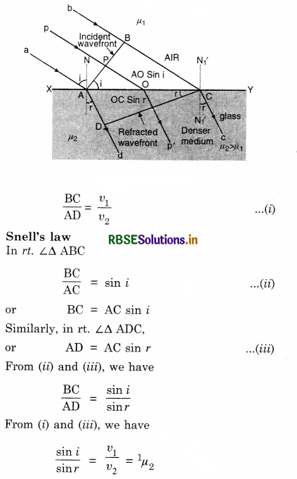
This is first law of refraction and is called Snell’s law.
Question 37.
How is a wavefront defined? Using Huygens’ principle draw a figure showing the propagation of a plane wave reflecting at the interface of the two media. Show that the angle of incidence is equal to the angle of reflection.
Answer:
Wavefront is the locus of all the points of the medium vibrating in the same phase.
Let XY be a plane refracting surface separating rarer medium I of refractive index µ1, from denser medium II of refractive index µ2 [µ2 > µ1], then
\(\frac{\mu_2}{\mu_1}=1 \mu_2=\frac{v_1}{v_2}\)
Where v1 is the velocity of light in medium I and v2 is the velocity of light in medium II.
According to Huygens’ principle, every point on incident wavefront AB is a source of secondary wavelets. By the time wavelet from point B reaches at point C, the wavelet from point A would have reached at point D s.t. time taken from B to C is equal to time taken from A to D.
i.e. t = \(\frac{\mathrm{BC}}{v_1}=\frac{\mathrm{AD}}{v_2}\)
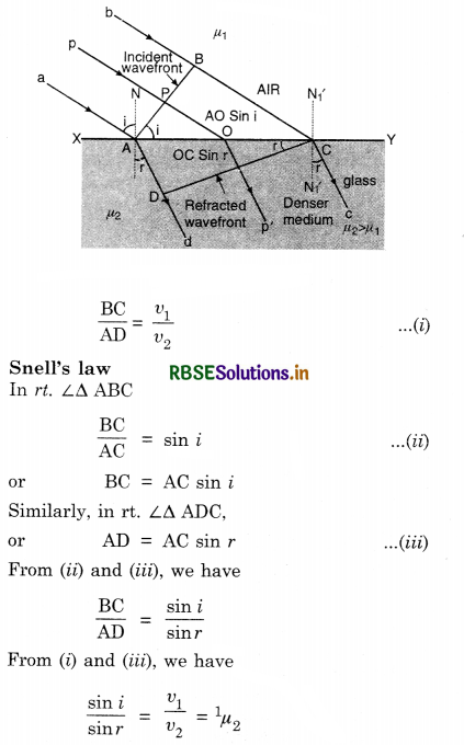
This is first law of refraction and is called Snell’s law.
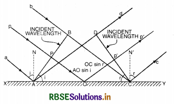
Let XY be a plane reflecting surface and AB be a plane wavefront incident on the surface as shown in Fig. SAQ 37.
According to Huygens’ principle, every point on wavefront AB is a source of secondary wavelets and the time during which wavelet from B reaches at C, the reflected wavelet from A would arrive at D.
If t is the time taken by wavelet from B to C [or A to D] then
t = \(\frac{\mathrm{BC}}{v}=\frac{\mathrm{AD}}{v}\)
or BC = AD .........................(i)
First law of reflection.
In rt. ∠∆ ABC,
\(\frac{\mathrm{BC}}{\mathrm{AC}}\) = sin i
or BC = AC sin i .......................(ii)
In rt. ∠∆ ADC,
\(\frac{\mathrm{AD}}{\mathrm{AC}}\) = sin r
or AD = AC sin r .......................(iii)
Putting Eq. (ii) and (iii) in Eq. (i), we get
AC sin i = AC sin r
or sin i = sin r
or i = r
i.e. Angle of incidence = Angle of reflection.
This proves first law of reflection.
Question 38.
How will the angular separation and visibility of fringes in Young’s double slit experiment change when
(i) screen is moved away from the plane of the slits, and
(ii) Width of the source-slit is increased.
Answer:
(i) Angular separation ß0 = is independent of the distance of the screen from the slits (D). Hence angular separation remains unchanged. But the actual separation of the fringes increases in proportion to the distance of the screen from the plane of the slits, so the visibility of fringes decreases.
(ii) On increasing the slit width, the angular fringe width remains unchanged. But the sharpness of fringes decreases and hence the visibility of the fringes decreases, and if the condition \(\frac{s}{S}<\frac{\lambda}{d}\) (s is the width of the source slit and S is its distance from the plane of the two slits) is not satisfied, the interference pattern disappears.
Question 39.
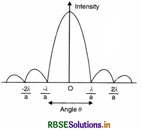
In a single slit diffraction experiment, the width of the slit is made double the original width. How does this affect the size and intensity of the central diffraction band? Draw a plot of intensity distribution.
Or
Draw the diffraction pattern due to a single slit by a monochromatic light.
Answer:
The size reduces by half according to the relation:
Size = \(\frac{\lambda}{d}\)
Intensity increases four fold. The intensity distribution graph is shown in Fig.
Question 40.
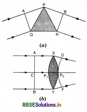
Draw the diagrams to show the behaviour of plane wavefronts as they pass through (a) a thin prism and (b) a thin convex lens.
Answer:
Following are the graphs:
Question 41.
Two identical coherent waves, each of intensity I, are producing an interference pattern. Find the value of the resultant intensity at a point
(i) constructive interference and
(ii) destructive interference.
Answer:
The resultant intensity at any point due to interference is given by
I' = I1 + I2 + 2\(\sqrt{\mathrm{I}_1 \mathrm{I}_2}\) cos Φ
Where Φ is the phase difference
Given I1 = I2 = I
So I' = I + I + 2\(\sqrt{\mathrm{I} . \mathrm{I}}\) cos Φ
= 2I (1 + cos Φ)
(i) At a point of constructive interference
Φ = 2nπ (n = 0, 1, 2, ....................)
So cos Φ = 1
∴ I'max = 2I (1 + 1) = 4I
(ii) At a point of destructive interference
Φ = (2n - 1) π (n = 0, 1, 2, ...................)
So cos Φ = 0
∴ I'min = 2I (1 - 1) = 0.

Question 42.
State three characteristic which distinguish interference pattern due to two coherently illuminated sources as compared to that observed in a diffraction pattern due to a single slit.
Or
Give two differences between interference and diffraction of light.
Answer:
Differences between interference and diffraction of light.
|
Interference |
Diffraction |
|
1. Interference takes place when light from two different wavefronts coming from two coherent sources superimpose on each other. |
1. Diffraction is due to superposition of secondary wavelets from various points on the same wave¬front. |
|
2. Bright fringes are of the same intensity. |
2. Intensity of seco¬ndary maximas goes on decreasing. |
|
3. Intensity of light is zero at minima. |
3. Intensity of light at minima is not zero. |
Question 43.
Two nearby narrow slits are illuminated by a single monochromatic source. Name the pattern obtained on the screen. One of the slits is now covered. What is the name of the pattern now obtained on the screen? Write two differences between the patterns obtained in the two cases.
Answer:
When two nearby narrow slits are illuminated by a single monochromatic source of light, wre get interference fringes on the screen i.e., we have alternatively bright and dark bands.
When one of the slits is covered, we have no interference pattern but have a general illumination on the screen. However, there may be a little diffraction pattern at the edge due to Fraunhoffer’s diffraction.
Differences. In first case, interference bands are alternatively bright and dark bands. All bands are of equal brightness.
In second case diffraction pattern at the edges are not of uniform brightness.
Question 44.
Two polaroids are placed at 90° to each other and the intensity of transmitted light is zero. What will be the intensity of transmitted light, when one or more polaroids is placed between these two bisecting the angle between them? Take intensity of unpolarised light as I0.
Answer:
The polaroid is placed bisecting the angle of 90° i.e. at 45°.
So intensity of emitted light is
I = I0 cos 45° = \(\frac{\mathrm{I}_0}{\sqrt{2}}\)
= 0.707 I0.
Question 45.
Three light rays red (R), green (G) and blue (B) are incident on a right angled prism ‘abc’ at face ‘ab’. The refractive indices of the material of the prism for red, green and blue wavelengths are 1.39, 1.44 and 1.47 respectively. Out of the three which colour ray will emerge out of face ‘ac’? Justify your answer. Trace the path of these rays after passing through face ‘ab’.
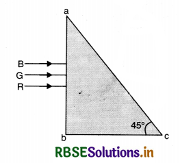
Answer:
For no emergence, the refractive index n should be greater than \(\frac{1}{\sin c}\)
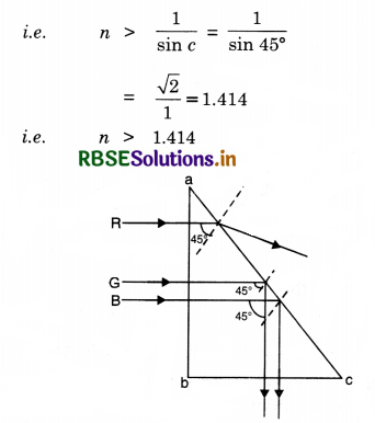
So the blue and green lights cannot emerge because their refractive index is more than 1.414 (ng = 1.44, nB = 1.47), and will suffer total internal reflection and only red light can emerge out because nr < 1.41. The path of these rays is shown in Fig. SAQ 45 (b).
Question 46.
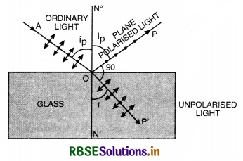
A beam of unpolarised light is incident on the boundary between two transparent media, If the reflected light is completely plane polarised, how is its direction related to the direction of the corresponding refracted light? Define Brewster’s angle. Obtain the relation between this angle and the refractive index for the given pair of media.
Answer:
The reflected light is perpendicular to the I direction of refracted light.
Brewster’s law. It state that the tangent of polarising angle is equal to the refractive index of transparent material.
i.e. tan ip = µ
or µ = tan ip
where ip is the polarising angle.
Proof. As shown in (Fig. LAQ 17 a) if ip is the angle of incidence (polarising angle) are r the corresponding angle of refraction, then according to
Brewster’s law.
∠POP' = 90°
∴ ip + r = 90°
or ip = 90° - r
or cos i = cos (90° - r) = sin r.
Now, if µ is the refractive index of the medium,
then
µ = \(\frac{\sin i_p}{\sin r}=\frac{\sin i_p}{\cos i_p}\)
Hence the tangent of the polarising angle is equal of the refractive index of the medium at which reflection takes place.
Question 47.
In a double slit experiment, the distance between the slits is 3 mm and the slits are 2 m away from the screen. Two interference patterns can be seen on the screen one due to light with wavelength 480 nm. and the other due to light with wavelength 600 nm. What is the separation on the screen between the fifth order bright 1 fringes of the two interference patterns?
Answer:
Given d = 3 mm = 3 x 10⁻³ m, D = 2m, λ1 = 480 nm = 480 x 10-9 m, λ2 = 600 nm = 600 x 10-9 m, ß1 = ?, ß2 = ?
Since fringe width ß is given by:
ß = \(\frac{\lambda \mathrm{D}}{d}\)
So for λ1 = 480 x 10-9 m, the width of 5th bright fringe
ß1 = \(\frac{\lambda \mathrm{D}}{d}=\frac{5 \times 480 \times 10^{-9} \times 2}{3 \times 10^{-3}}\) = 16 x 10-4 m
For λ2 = 600 x 10-9 m, the width of 5th bright fringe
ß2 = \(\frac{5 \lambda_2 \mathrm{D}}{d}=\frac{5 \times 600 \times 10^{-9} \times 2}{3 \times 10^{-3}}\) = 20 x 10-4 m
∴ Distance between two 5th bright fringes on the screen = ß2 - ß1 = (20 - 16) x 10-4 = 4 x 10⁻⁴ m.

Question 48.
What do you understand by the statement ‘Light from the sun is unpolarised’? Explain how does sunlight get polarized by the process of scattering.
Answer:
Light from sun is unpolarised means that the electric vector of the sunlight vibrate in all possible directions in a transverse plane.
Polarisation by scattering
The incident sunlight is unpolarised. The dots stand for polarisation perpendicular to the plane of the figure. The double arrows show polarisation in the plane of the paper. When this light becomes incident on nitrogen molecules of the atmosphere, electrons of the molecules are set into vibration in these two perpendicular directions and are accelerated.
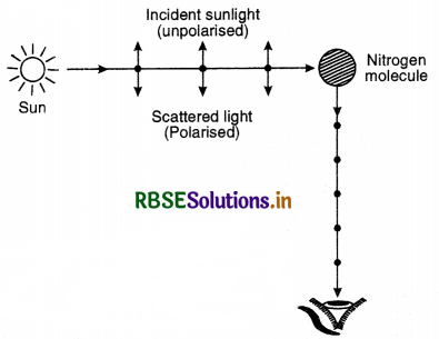
The observer is looking in a direction at 90° to the direction of sun. The electrons accelerating parallel to the double arrows do not radiate energy towards the observer. The electrons accelerating along dot radiate energy towards the observer. The radiation scattered towards the observer is therefore, represented by dots. The radiation is polarised perpendicular to the plane of the paper (Fig LAQ 17.39). It is polarised perpendicular to the plane of the figure. A plane at right angle to the plane of vibration of light wave is called plane of polarisation.
Question 49.
(a) If one of two identical slits producing interference in Young’s experiment is covered with glass, so that the light intensity passing through it is reduced to 50% find the ratio of the maximum and minimum intensity of the fringe in the interference pattern.
(b) What kind of fringes do you expect to observe if white light is used instead of monochromatic light?
Answer:
(a) Let I1 = I, So I2 = I/2
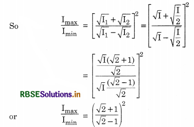
(b) When white light is used, the central fringe is white and few coloured fringes are formed and there is no clear fringe pattern is seen.
Question 50.
Define the term wavefront. Using Huygens theory, verify the law of reflection.
Answer:
Wavefront is the locus of all the points of the medium vibrating in the same phase.
Let XY be a plane refracting surface separating rarer medium I of refractive index µ1, from denser medium II of refractive index µ2 [µ2 > µ1], then
\(\frac{\mu_2}{\mu_1}=1 \mu_2=\frac{v_1}{v_2}\)
Where v1 is the velocity of light in medium I and v2 is the velocity of light in medium II.
According to Huygens’ principle, every point on incident wavefront AB is a source of secondary wavelets. By the time wavelet from point B reaches at point C, the wavelet from point A would have reached at point D s.t. time taken from B to C is equal to time taken from A to D.
i.e. t = \(\frac{\mathrm{BC}}{v_1}=\frac{\mathrm{AD}}{v_2}\)
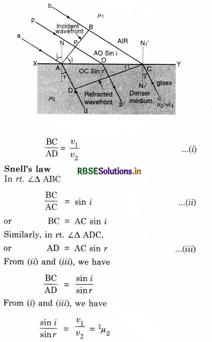
This is first law of refraction and is called Snell’s law.
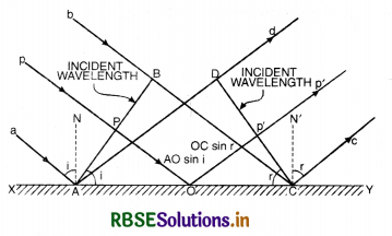
Let XY be a plane reflecting surface and AB be a plane wavefront incident on the surface as shown in Fig. SAQ 37.
According to Huygens’ principle, every point on wavefront AB is a source of secondary wavelets and the time during which wavelet from B reaches at C, the reflected wavelet from A would arrive at D.
If t is the time taken by wavelet from B to C [or A to D] then
t = \(\frac{\mathrm{BC}}{v}=\frac{\mathrm{AD}}{v}\)
or BC = AD .........................(i)
First law of reflection.
In rt. ∠∆ ABC,
\(\frac{\mathrm{BC}}{\mathrm{AC}}\) = sin i
or BC = AC sin i .......................(ii)
In rt. ∠∆ ADC,
\(\frac{\mathrm{AD}}{\mathrm{AC}}\) = sin r
or AD = AC sin r .......................(iii)
Putting Eq. (ii) and (iii) in Eq. (i), we get
AC sin i = AC sin r
or sin i = sin r
or i = r
i.e. Angle of incidence = Angle of reflection.
This proves first law of reflection.
Question 51.
Define the term, refractive index of a medium. Verify Snell’s law of refraction when a plane wavefront is propagating from denser to a rarer medium.
Answer:
Refractive index of a medium is the ratio of velocity of light in vacuum to the velocity of light in that medium.
i.e. µ = \(\frac{c}{v}\)
Snell's law of refraction
Wavefront is the locus of all the points of the medium vibrating in the same phase.
Let XY be a plane refracting surface separating rarer medium I of refractive index µ1, from denser medium II of refractive index µ2 [µ2 > µ1], then
\(\frac{\mu_2}{\mu_1}=1 \mu_2=\frac{v_1}{v_2}\)
Where v1 is the velocity of light in medium I and v2 is the velocity of light in medium II.
According to Huygens’ principle, every point on incident wavefront AB is a source of secondary wavelets. By the time wavelet from point B reaches at point C, the wavelet from point A would have reached at point D s.t. time taken from B to C is equal to time taken from A to D.
i.e. t = \(\frac{\mathrm{BC}}{v_1}=\frac{\mathrm{AD}}{v_2}\)
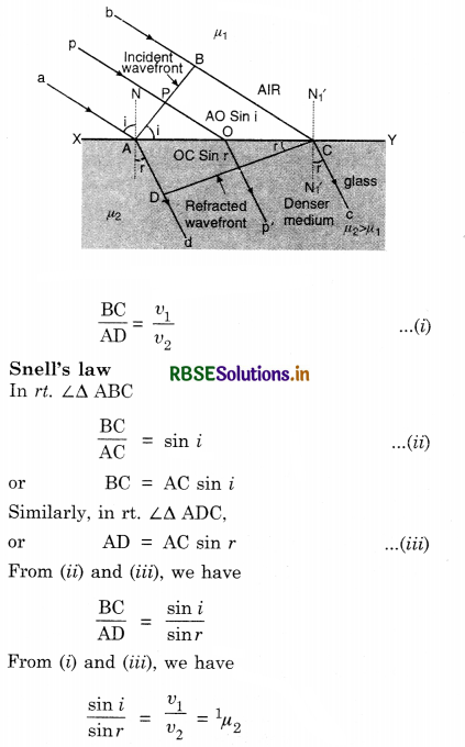
This is first law of refraction and is called Snell’s law.
Long Answer Type Questions
Question 1.
(a) Define wavefront and a ray.
(b) What are types of wavefront?
Answer:
Wavefront. Wavefront is defined as the locus of the neighbouring particles of the medium which are in the same phase of disturbance.
The line along which energy is propagated is called a ray. It is ⊥ wavefront at any point. In Fig. LAQ 1 (a) the concentric spheres represent spherical wavefronts with the source of light at O.
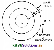
Types of wavefront
1. Spherical wavefront. A wavefront due to point source in a three dimensional isotropic space is called spherical wavefront.
Consider a point source of light placed in an isotropic medium i.e., a medium in which the velocity of light is the same in all directions. The disturbance from the point source travels equally in all directions.
If c = velocity of light, then after time t. light will have travelled a distance equal to ct in all directions. The locus of all points where light reaches after time t will be a sphere. A set of spherical wavefront represents a diverging beam of light [Fig. LAQ 1 (b)]
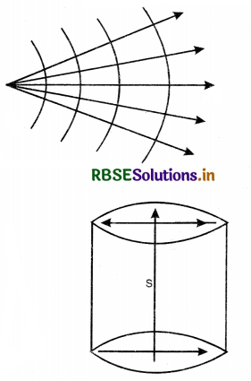
2. Cylindrical wavefront. When the slit is a source of light, all points equidistant from the source lie, on a cylinder. Therefore, wavefront is cylindrical [Fig. LAQ 1 (c)].
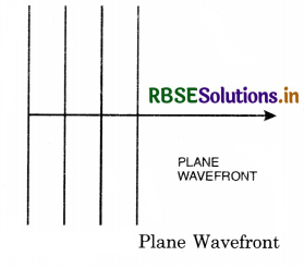
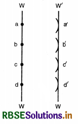
3. Plane wavefront. When the source is at infinite distance, the radius of curvature of wavefront will be very large.
A small portion of spherical wavefront with source at infinite distance is a plane wavefront. [Fig. LAQ 1 (d)].

Question 2.
State Huygens’ principle. What steps are involved in constructing a wavefront?
Answer:
Huygens’ Principle
It is based on the following two assumptions:
(1) All the particles on a given wavefront (Called primary wavefront) can be regarded as point sources of new disturbance called the secondary wavelets which travel out with the same velocity as that of the original waves, provided the medium is the same.
(2) A surface tangential to the secondary wavelets gives the position and shape of the new wavefront.
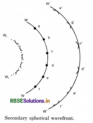
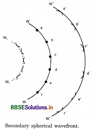
Illustration. Consider O to be a point source of light and WW a spherical wavefront originating from it (Fig. LAQ 2 (a)) All the points a, b, c,... on this will be vibrating in unison and may be regarded as sources of secondary disturbances. To find the position of the wavefront after an interval t second, draw spheres of radius ct (where c is the velocity of light) with a, b, c,... as centre which wall be Huygens' secondary waves. These waves touch a sphere W'W' whose centre is at O. The spherical surface constitutes the new secondary wavefront which is also spherical.
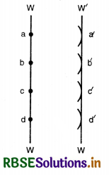
If the source of light is at a large distance, we will have a plane wavefront as shown in Fig. LAQ 2 (b).
Referring again to Fig. LAQ 2 (a), it will be seen that the secondary wavelets spread out in the backward direction also, and W1W1 represents the envelope of these back portions of the waves by dotted lines. Thus W1W1 is also a secondary wavefront which in reality does not exist. To account for this difficulty, it is assumed that the only effective part of the secondary wavelets is the portion which lies on the forward secondary wavefront. The remaining part of the secondary wavelet is ineffective. Thus, there are no back waves and the wavefront W1W1 is absent.
Question 3.
Show that angle of incidence is equal to angle of reflection and also they lie in the same plane.
Or
Using Huygens’ principle, derive laws of reflection.
Answer:
Let XY be a plane reflecting surface and AB be a plane wavefront incident on the surface as shown in Fig. LAQ 3.
According to Huygens’ principle, every point on wavefront AB is a source of secondary wavelets and the time during which wavelet from B reaches at C, the reflected wavelet from A would arrive at D.
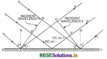
If t is the time taken by wavelet from B to C [or A to D] then
t = \(\frac{\mathrm{BC}}{v}=\frac{\mathrm{AD}}{v}\)
or BC = AD ......................(i)
First law of reflection.
In rt. ∠∆ ABC,
\(\frac{\mathrm{BC}}{\mathrm{AC}}\) = sin i
or BC = AC sin i ........................(ii)
In rt. ∠∆ ADC,
\(\frac{\mathrm{AD}}{\mathrm{AC}}\) = sin r
or AD = AC sin r .......................(iii)
Putting Eq. (ii) and (iii) in Eq. (i), we get
AC sin i = AC sin r
or sin i = sin r
or i = r
i.e. Angle of incidence = Angle of reflection.
This proves first law of reflection.
Second law of reflection
Since incident ray, reflected ray and the normal all lie on the same plane i.e. plane XY, so second law of reflection is also proved.

Question 4.
(a) Prove Snell's law using Huygens’ principle.
(b) Show how wavefronts behave while passing through a prism and a lens.
Or
State Huygens’ principle. With the help of suitable diagram, prove Snell’s law of refraction using Huygens’ principle.
Answer:
Huygens’ Principle
It is based on the following two assumptions:
(1) All the particles on a given wavefront (Called primary wavefront) can be regarded as point sources of new disturbance called the secondary wavelets which travel out with the same velocity as that of the original waves, provided the medium is the same.
(2) A surface tangential to the secondary wavelets gives the position and shape of the new wavefront.
Illustration. Consider O to be a point source of light and WW a spherical wavefront originating from it (Fig. LAQ 2 (a)) All the points a, b, c,... on this will be vibrating in unison and may be regarded as sources of secondary disturbances. To find the position of the wavefront after an interval t second, draw spheres of radius ct (where c is the velocity of light) with a, b, c,... as centre which wall be Huygens' secondary waves. These waves touch a sphere W'W' whose centre is at O. The spherical surface constitutes the new secondary wavefront which is also spherical.
If the source of light is at a large distance, we will have a plane wavefront as shown in Fig. LAQ 2 (b).
Referring again to Fig. LAQ 2 (a), it will be seen that the secondary wavelets spread out in the backward direction also, and W1W1 represents the envelope of these back portions of the waves by dotted lines. Thus W1W1 is also a secondary wavefront which in reality does not exist. To account for this difficulty, it is assumed that the only effective part of the secondary wavelets is the portion which lies on the forward secondary wavefront. The remaining part of the secondary wavelet is ineffective. Thus, there are no back waves and the wavefront W1W1 is absent.
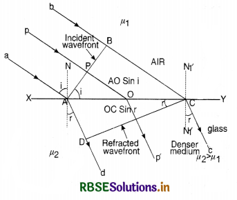
(a) Let XY be a plane refracting surface separating rarer medium I of refractive index µ1, from denser medium II of refractive index µ2 [µ2 > µ1], then
\(\frac{\mu_2}{\mu_1}=1 \mu_2=\frac{v_1}{v_2}\)
Where v1 is the velocity of light in medium I and v2 is the velocity of light in medium II.
According to Huygens’ principle, every point on incident wavefront AB is a source of secondary wavelets. By the time wavelet from point B reaches at point C, the wavelet from point A would have reached at point D s.t. time taken from B to C is equal to time taken from A to D.
i.e. t = \(\frac{\mathrm{BC}}{v_1}=\frac{\mathrm{AD}}{v_2}\)
\(\frac{\mathrm{BC}}{\mathrm{AD}}=\frac{v_1}{v_2}\) ..........................(i)
First law of refraction
In rt. ∠∆ ABC,
\(\frac{\mathrm{BC}}{\mathrm{AC}}\) = sin i
or BC = AC sin i ........................(ii)
Similarly, in rt. ∠∆ ADC,
\(\frac{\mathrm{AD}}{\mathrm{AC}}\) = sin r
or AD = AC sin r .......................(iii)
From (ii) and (iii), we have
\(\frac{\mathrm{BC}}{\mathrm{AD}}=\frac{\sin i}{\sin r}\)
From (i) and (iii), we have
\(\frac{\sin i}{\sin r}=\frac{v_1}{v_2}\) = 1µ2
This is first law of refraction and is called Snell’s law.
Second law of refraction. Since incident ray, refracted ray and the normal, all lie on the same plane XY at the point of incidence. This proves second law of refraction.
(b) Behaviour of wavefront while passing through:
(i) Prism
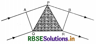
Consider a small angled prism PQR and a plane wavefront AQ incident on the prism. The course of rays is as shown is Fig. (b). According to Huygens’ principle, every point on wavefront AQ is the source of secondary wavelets. The secondary wavelets from Q travel through the material of the prism and the secondary wavelets from A travel almost in air, and the other wavelets travel different thicknesses of the glass prism. Since the speed of light in glass is less than the speed of light in air thus the ray of light bends towards the base after passing through the prism.
(ii) Lens
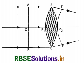
Consider a convex lens XY as shown in Fig. LAQ 4 (c) and a plane wavefront AB incident on it. The course of rays is as shown in the figure. According to Huygens’ principle, every point on wavefront AB is the source of secondary wavelets. The secondary wavelets from A or B travel almost through air and the secondary wavelets from C travel a distance P1P2 almost inside the material of the lens. Since speed of fight in glass is less than the speed of fight in air. Thus the rays of fight takes the form of spherical wave form DP2F.
Question 5.
State and explain principle of superposition of waves.
Answer:
Superposition principle. It states that when a number of waves travelling simultaneously in the same medium overlap one another (superimpose), then the resultant displacement at any instant at any point in space is equal to the vector sum of the instantaneous displacements of individual waves.
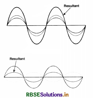
If \(\vec{y}_1, \vec{y}_2, \ldots \ldots, \vec{y}_n\) are displacements of n individual waves at any instant, then the displacement of resultant wave \(\vec{y}\) will be
\(\vec{y}=\vec{y}_1+\vec{y}_2+\ldots \ldots \ldots \vec{y}_n\)
Consider two waves which are superimposing on each other as shown in Fig. If crest of one falls on the crest of other, the resultant amplitude will increase Fig. LAQ 5(a) and if crest of one falls on trough of other, the resultant amplitude will decrease Fig. LAQ 5 (b). The principle of superposition is used to explain the interference of light.

Question 6.
Explain coherent sources.
Answer:
Coherent sources. Two sources are said to be coherent if they emit waves of the same frequency and with constant phase difference or no phase difference.
Consider two sources producing electric fields\( \overrightarrow{\mathrm{E}}_1\) and \(\overrightarrow{\mathrm{E}}_2\) respectively at a given point.
The total electric field at a point, due to superposition of field is
\(\overrightarrow{\mathrm{E}} = \overrightarrow{\mathrm{E}}_1 + \overrightarrow{\mathrm{E}}_2\)
∴ Intensity of wave at that point is I ∝ E2
I = kE2
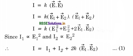
The term 2k \(\left(\vec{E}_1 \cdot \vec{E}_2\right)\) is called interference term. All practical measurements give the intensity of light averaged over many oscillations of the wave. Therefore, the average value of the interference term is to be considered.
Special case
(i) When \(\overrightarrow{\mathrm{E}}_1 \perp \overrightarrow{\mathrm{E}}_2\) i.e., θ = 90°,
∴ 2k\(\left(\overrightarrow{\mathrm{E}}_1 \cdot \overrightarrow{\mathrm{E}}_2\right)\) = 2E1, E cos 90° = 0
∴ From Eq. (1), I = I1 + I2
i.e., Intensities of two sources just get added up.
(ii) When \(\overrightarrow{\mathrm{E}}_1\) || \(\overrightarrow{\mathrm{E}}_2\) i.e., θ = 0
∴ 2 \(\left(\vec{E}_1 \cdot \vec{E}_2\right)\) = 2E1E2 .......................(2)
Let a1 = amplitude of wave for one source
ω1 = angular frquency of source
Φ1 = initial phase
a2 = amplitude of wave for 2nd source
ω2 = angular frequency of source
Φ2 = initial phase for 2nd source
∴ From Eq. (2),
2kE1 E2 = 2ka1 cos (ω1t + Φ1) x a2 cos (ω2t + Φ2)
= 2ka1a2 cos (ω1t + Φ1) cos (ω2t + Φ2)
= ka1a2 [cos {(ω1 + ω2)t + Φ1 + Φ2} + cos {(ω1 - ω2) t + Φ1 + Φ2}] .............................(3)
[∵ 2 cos A cos B = cos (A + B) + cos (A - B)]
(a) It is clear that if two frequencies ω1 and ω2 are different, then both the terms in eq. (3) are of the form cos θ and θ varies with time.
The average value of cos θ is zero if angle θ is allowed to vary between 0° and 360°.
∴ For two different frequencies, the interference term has a zero average.
(b) If ω1 = ω2
∴ From Eq. (3),
2E1E2 = a1a2 cos (Φ1 - Φ2)
∴ Interference term depends upon the phase difference (Φ1 - Φ2)
If this phase difference varies from 0° to 360°,
∴ the average value will be zero.
But if two sources have the same frequency and either possess phase difference or constant phase difference then this term will survive and will give rise to interference i.e. rise or fall in resultant intensity. Such sources are called Coherent Sources.
Conditions for two sources to be coherent are:
(i) They must have the same frequency.
(ii) The phase difference should be stable or there should be no phase difference between the waves.
Lloyd single mirror, Fresnel double mirror, Fresnel biprism, Young's double slit etc. are the methods of obtaining coherent sources.

Question 7.
Explain the terms interference of light and define constructive and destructive interference. Is law of conservation of energy obeyed?
Answer:
Interference of Light. The phenomenon of redistribution of energy in a medium due to superimposition of waves from two coherent sources of light is called Interference of Light.
Constructive Interference. At points, where the crest of one wave falls on the crest of the other or a trough of one falls on the trough of the other, the amplitude of the resulting wave becomes maximum. Hence the energy or the intensity of light at such points becomes maximum. This is called Constructive Interference.
Destructive Interference. At some other points where the trough of one falls on the crest of the other or crest of one falls on the trough of the other, the amplitude of the resulting waves becomes minimum. Hence the energy or intensity becomes minimum. This is called Destructive Interference.
Law of conservation of energy is obeyed. It should be clearly understood that in interference of light no light energy is destroyed. The loss of energy at the points of destructive interference appears as the increase of energy at the points of constructive interference.
Question 8.
What is sustained interference? What are necessary conditions for producing stationary or sustained interference.
Answer:
Sustained interference. The interference in which the position of maxima and minima of light remains fixed all along the screen is called sustained interference.
Conditions for sustained interference. To produce sustained (or stationary) interference following conditions should be fulfilled:
- Two sources must be coherent, so the sources emit continuous waves of the same wavelength (or frequency) which are either in the same phase or a constant phase difference.
- The waves should be preferably of the same amplitude to get complete darkness in case of destructive interference.
- Two sources must be very close to each other, if it is not so, the path difference at particular point of observation will be large and the maximas will be very close to each other and may overlap.
(∵ ß ∝ \(\frac{1}{(\text { distance between the sources) }}\)) - Two sources must be very narrow, a broad source of light is equivalent to a large number of narrow sources and each set of two sources will give its own interference pattern and their overlap will result in general illumination.
- The distance between two sources and the screen should be large, so that the dark and bright fringes are of large width [∵ ß ∝ D (distance between two sources and screen)].
Question 9.
What are coherent sources of light? Draw the variation of- intensity with position, in the interference pattern of Young's double slit experiment.
Or
Describe the condition for constructive and destructive interference.
Answer:
Coherent sources. Coherent sources are those sources which emit continuously light of the same wavelength and magnitude either in the same phase or with a constant phase difference.
Expression
Let the waves of two coherent sources be
y1 = a sin ωt
and y2 = b sin (ωt + Φ),
where a and b are the respective amplitudes of the two waves and Φ is the constant phase angle by which the second wave leads the first wave [Fig].
According to superposition principle, the displacement y of resultant wave is
y = y1 + y2 = a sin ωt + b sin (ωt + Φ)
or y = a sin ωt + b sin ωt cos Φ + b cos ωt sin Φ
or y = sin ωt (a + b cos Φ) + cos ωt. b sin Φ
Substituting a + b cos Φ = A cos θ ......................(1)
and b sin Φ = A sin θ ....................(2)
we have
y = sin ωt. A cos θ + cos ωt. A sin θ
or y = A [sin ωt. cos θ + cos ωt. sin θ]
or y = A sin (ωt + θ),
where A is the amplitude of the resultant wave. Squaring and adding (1) and (2), we have
a2 + b2 cos2 Φ + 2ab cos Φ + b2 sin2 Φ
= A2 cos2 θ + A2 sin2 θ
or a2 + b2 (cos2 Φ + sin2 Φ + 2ab cos θ)
= A2 (cos2 θ + sin2 θ)
or A2 = a2 + b2 + 2ab cos Φ
Since resultant intensity is proportional to square of amplitude,
∴ I ∝ A2
or I ∝ (a2 + b2 + 2ab cos Φ)
or I = a2 + b2 + 2 ab cos Φ ........................(3)
(For convenience, we assume that intensity of light is equal to square of amplitude)
(i) For constructive interference (or for maximum).
I should be maximum
i.e. cos Φ = 1 and Imax = (a + b)2
or Φ = 0, 2π, 4π, ..........................
or Φ = 2π n (where n = 0, 1, 2, ......................)
or Path diff. = \(\frac{\lambda}{2 \pi}\)Φ = \(\frac{\lambda}{2 \pi}\) 2πn = n λ ...........................(4)
So, for constructive interference (or for maximum intensity), path difference should be integral multiple of λ.
(ii) For destructive interference (or for minima)
I should be minimum
i.e. cos Φ = -1 and Imin = (a - b)2
or Φ = π, 3π, 5π, ..........................
or Φ = (2n + 1) π (where n = 0, 1, 2, ......................)
or path difference = \(\frac{\lambda}{2 \pi}\) (2n + 1) π
= (2n + 1) \(\frac{\lambda}{2}\) .........................(5)
So, for destructive interference (or for minimum intensity), path difference should be an odd multiple of λ/2.
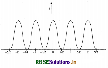
Variation of intensity with position
From above discussion, we find that intensity of light is maximum when path difference is nλ i.e. ±λ, 2λ, 3λ ............... and minimum when path difference is (2 n+ 1) λ/2
i.e. ± \(\frac{\lambda}{2}\), 3\(\frac{\lambda}{2}\), 5\(\frac{\lambda}{2}\) ...................
The variation in intensity of light with position in interference is as shown in Fig. LAQ 9 (b).

Question 10.
Show that in Young’s double slit experiment for interference of light, the widths of the bright and dark fringes are equal.
Or
Derive an expression for fringe width using Young’s double slit method for interference of light. What will happen if the distance between the two slits becomes nearly zero?
Or
In Young’s double slit experiment deduce the condition for (i) constructive and (ii) destructive interference at a point on the screen. Draw a graph showing variation of the resultant intensity in the interference pattern against position ‘X’ on the screen.
Or
Describe Young’s double slit experiment and obtain an expression for the fringe width.
Answer:
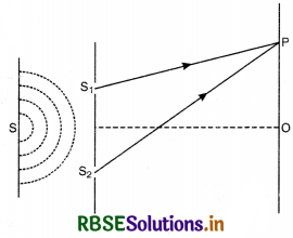
Let S1, S2 be the two fine slits illuminated by a monochromatic source S of wavelength A.
Intensity of light at any point P on the screen at a distance D from the slit depends upon the path difference between S2P and S1P.
Let O be a point on the screen equidistant from S1 and S2, so path difference S1O and S2O is zero. Hence this point will have maximum intensity due to constructive interference and is called central fringe.
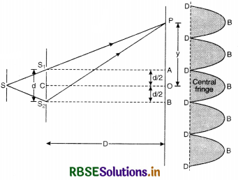
Let point P be lying on the screen at a distance y from O as shown in Fig. LAQ 10.
∴ Path difference between two waves reaching at P.
= S2P - S1P
In rt. ∠∆ S2BP, we have
(S2P)2 = (S2B)2 + (PB)2
or (S2P)2 = D2 + \(\left(y+\frac{d}{2}\right)^2\) ...........................(1)
In rt. ∠∆ S1AP, we have
(S1P)2 = (S1A)2 + (PA)2
or (S1P)2 = D2 + \(\left(y-\frac{d}{2}\right)^2\) ............................(2)
Subtracting Eq.(2) from Eq. (1), we get
(S2P)2 - (S1P)2 = \(\left(y+\frac{d}{2}\right)^2-\left(y-\frac{d}{2}\right)^2\)
or (S2P + S1P) (S2P - S1P) = 4y\(\frac{d}{2}\)
OR S2P - S1P = \(\frac{2 y d}{\mathrm{~S}_2 \mathrm{P}+\mathrm{S}_1 \mathrm{P}}\)
Since point P is very close to A and B
So S2P ≈ S1P ≈ D
∴ S2P - S1P = \(\frac{2 y d}{\mathrm{D}+\mathrm{D}}=\frac{y d}{\mathrm{D}}\)
∴ Path difference (S2P - S1P) = \(\frac{y d}{\mathrm{D}}\) ...........................(3)
(i) For construction interference [Bright Fringes]. For bright fringes, the path difference should be equal to integral multiple of d.
\(\frac{y d}{\mathrm{D}}\) = nλ
or y = n\(\frac{\lambda \mathrm{D}}{d}\)
If n = 0; y0 = 0, which is the position of central maxima.
If n = 1; y1 = \(\frac{\mathrm{D}}{d}\)λ, which is the position of first maxima.
If n = 2; y2 = \(\frac{2 \mathrm{D}}{d}\)λ, which is the position of 2nd maxima
Similarly, yn-1 = (n - 1) \(\frac{\mathrm{D}}{d}\)λ
and yn = n\(\frac{\mathrm{D}}{d}\)λ
Fringe width, ß = yn - yn-1
= \(\frac{\mathrm{D}}{d}\)y [n - (n - 1)]
ß = \(\frac{\mathrm{D}}{d}\)y ...............................(4)
(ii) For destructive interference [Dark Fringes]. For dark fringes, the path difference should be an odd multiple of λ/2.
\(\frac{\mathrm{D}}{d}\)y = (2n - 1) λ/2
or y = \(\frac{\mathrm{D}}{d} (2n - 1) \frac{\lambda}{2}\)
If n = 1; y1 = \(\frac{\mathrm{D}}{d} \frac{\lambda}{2}\), (which is the position of 1st minima.)
If n = 2; y2 = \(\frac{\mathrm{D}}{d} \frac{3 \lambda}{2}\), (which is the position of 2nd minima.)
If n = 3; y3 = \(\frac{\mathrm{D}}{d} \frac{5 \lambda}{2}\), (which is the position of 3rd minima.)
∴ Fringes width, ß = y3 - y2 = \(\frac{\mathrm{D}}{d}\) λ
or ß = \(\frac{\mathrm{D}}{d}\) λ ..............................(5)
From (4) and (5), we conclude that bright and dark fringes have equal fringe width
ß ∝ D
∝ λ
∝ \(\frac{1}{d}\)
If d = 0, ß = ∞ i.e. dark and bright bands will be infinitely well spaced and there will be uniform illumination.
Conclusions
- ß does not depend upon n so that all fringes have the same width.
- For fixed wavelength λ and separation d fringe width ß increases as D increases. Therefore, the dark fringes become darker and bright becomes less brighter. If D is very large, the two types of fringes become indistinguishable giving a sense of general illumination. Therefore, for good fringes the screen should not be too far off.
- For fixed D and λ, the fringe width ß is more if d decreases. This is why the two sources are kept very close for good fringes.
- Separation ∆ß between two adjacent bright or dark fringes subtend angle ∆θ at the centre O of the double slit
∆θ = \(\frac{\beta}{\mathrm{D}}=\frac{\lambda}{d}\)
The angular separation of fringes is given by \(\frac{\lambda}{d}\) and is independent of the position of the screen. It, therefore, gives a dirct way of measuring λ, the wavelength of light. - Interference pattern with white light. When slits are illuminated with white light, only central maxima is white (∵ at O, y = 0, n = 0 for all values of λ). All other bright lines become coloured. Coloured lines have their violet edges towards central maxima because y ∝ λ.
Note. For clear interference pattern, lines must be wide, for which d must be small. Hence the two coherent sources must be very close.

Question 11.
What is interference of light? Write two essential conditions for sustained interference pattern to be produced on the screen.
Draw a graph showing the variation of intensity verses the position on the screen in Young’s experiment, when
(a) both the slits are opened
(b) one of the slits is closed.
What is the effect on interference pattern in Young’s double slit experiment when
(i) screen is moved closer to the plane of slits?
(ii) separation between two slits is increased. Explain your answer in each case.
Answer:
Interference of Light. The phenomenon of redistribution of energy in a medium due to superimposition of waves from two coherent sources of light is called Interference of Light.
Constructive Interference. At points, where the crest of one wave falls on the crest of the other or a trough of one falls on the trough of the other, the amplitude of the resulting wave becomes maximum. Hence the energy or the intensity of light at such points becomes maximum. This is called Constructive Interference.
Destructive Interference. At some other points where the trough of one falls on the crest of the other or crest of one falls on the trough of the other, the amplitude of the resulting waves becomes minimum. Hence the energy or intensity becomes minimum. This is called Destructive Interference.
Law of conservation of energy is obeyed. It should be clearly understood that in interference of light no light energy is destroyed. The loss of energy at the points of destructive interference appears as the increase of energy at the points of constructive interference.
Conditions for sustained interference. To produce sustained (or stationary) interference following conditions should be fulfilled:
- Two sources must be coherent, so the sources emit continuous waves of th same wavelength (or frequency) which are either in the same phase or a constant phase difference.
- The waves should be preferably of the same amplitude to get complete darkness in case of destructive interference.
- Two sources must be very close to each other, if it is not so, the path difference at particular point of observation will be large and the maximas will be very close to each other and may overlap.
(∵ ß ∝ \(\frac{1}{(\text { distance between the sources) }}\)) - Two sources must be very narrow, a broad source of light is equivalent to a large number of narrow sources and each set of two sources will give its own interference pattern and their overlap will result in general illumination.
- The distance between two sources and the screen should be large, so that the dark and bright fringes are of large width [∵ ß ∝ D (distance between two sources and screen)].
Graphs
(a) When both the slits are opened See Fig. LAQ 11.
(b) When one of the slits is closed
The graph is shown in Fig. 11 for S1 or S2.
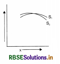
Since fringe width, ß = \(\frac{\lambda \mathrm{D}}{d}\)
So (i) when screen is moved closer to the plane of slits, D decreases and hence ß will also decrease.
(ii) When separation between the slits is increased, d increases and hence ß will decrease.

Question 12.
Explain clearly what is diffraction of light?
Answer:
Diffraction. The bending of light round corners and spreading it into the regions of geometrical shadows as it passes through an aperture or across an obstacle in their path is called diffraction of light.
When a narrow slit AB is placed in path of the light, then only part A'B' of the screen should be illuminated and no light should enter the regions A'X and BY of the screen [Fig. LAQ 12 (a)]. On the other hand, when obstacle AB is placed, then its distinct geometrical shadow A'B' should be obtained [Fig. LAQ 12 (b)].
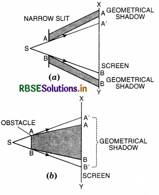
It happens exactly so only when size of slit or obstacle is large. However, if the size of the slit or obstacle is made small, then light enters in the geometrically prohibited regions showing thereby that the light bends round the corners of the slit or obstacle.
This phenomenon of bending of light round the corners and spreading into the regions of the geometrical shadow is called diffraction.
In principle, all the types of wave motion exhibit diffraction effect. The diffraction of radio waves and sound waves is readity observed in practice.
Condition for diffraction. The light waves are diffracted only when the size of the obstacle is comparable to the wavelength of the light.
Question 13.
(a) Discuss the diffraction produced by a narrow slit which is illuminated by monochromatic light.
(b) Show that the central maximum in the single slit diffraction is twice as wide as the second maxima and the pattern becomes narrow as the width of slit is increased.
Or
Using Huygens’ principle, draw a diagram to show propagation of wavefront originating from a monochromatic point source.
Or
Describe the diffraction of light due to a single slit. Explain fromation of a pattern of fringes obtained on the screen and plot showing the variation of intensity with angle 6 in single slit diffraction.
Answer:
Huygens’ principle and the diagram for propagation of w avefront.
Assumptions on which Huygens’ principle is based are:
- The medium is homogeneous.
- The medium is isotropic.
Huygens’ principle
(a) Each point of a wavelength becomes a source of new disturbance called the secondary wavelets which travel in all directions with the same speed provided the medium remains the same.
(b) The secondary wavefront is the tangent plane joining all the wavefronts.
Fig. SAQ 1 (a) represents the trace of secondary wavefront at a certain instant and Fig. SAQ 1 (b) represents the trace when the light has travelled a large distance.
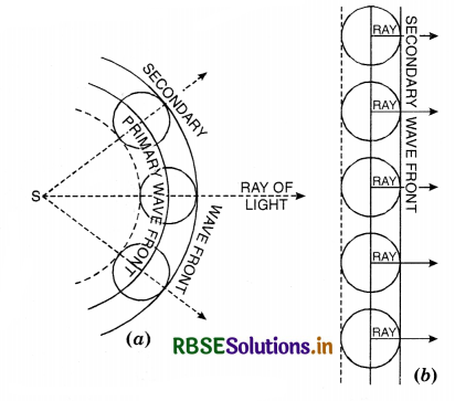
Rays of light are perpendicular to the wavefront.
(a) Diffraction of light by narrow slit
Consider a narrow slit AB perpendicular to plane of paper on which a monochromatic light be incident normally. Due to diffraction pattern consists of a central band much wider than the slit width just opposite to the slit and bordered on either side by dark and bright fringes of decreasing intensity. It is found that
- the intensity of the secondary maxima goes on decreasing.
- the width of central maximum is double that of a secondary maximum.
Consider a plane wavefront WW incident on the slit AB (Fig. LAQ 13). Imagine the slit to be divided into a large number of very narrow strips of equal width parallel to the slit. When the wavefront reaches the slit, each narrow strip parallel to the slit can be considered to be a source of Huygens’ secondary wavelets.
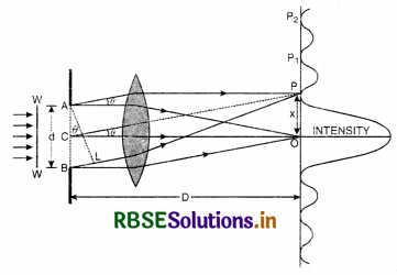
Central Maxima. Let us first consider the effect of all the wavelets at the point O just opposite to the middle of the slit. Since distance between the slit and the screen is very large as compared wdth the width of the slit, the wavelets cover the same distance and reach O in the same phase. Thus the wavelets reinforce each other’s effect to give maximum intensity at O.
Position of secondary minima
Let us now consider the intensity at a point P above O produced by the rays travelling at an ∠θ with the original direction. Since the width of the slit is very small, all the rays reaching P proceed almost parallel to each other. The wavelets from all the points in the slit start in the same phase but as they travel different distances, they reach P in different phases. Draw AL normal to BP.
The path difference between the extreme rays is BP - AP = BL.
Let C be the mid-point of slit or path difference between AP and CP = \(\frac{\lambda}{2}\)
∴ Wavelets starting from A and C shall reach the point P in opposite phases and cancel each other’s effect.
Similarly, the wavelets from a strip below A are cancelled by the wavelets from a corresponding strip below C.
In ∆ ABL,
\(\frac{\mathrm{BL}}{\mathrm{AB}}\) = sin θ
∴ BL = AB sin θ
or BL = d sin θ
For first minima, BL = λ;
∴ d sin θ = λ
or sin θ = \(\frac{\lambda}{d}\)
Since θ is small ∴ sin θ = θ = \(\frac{x}{\mathrm{D}}\)
\(\frac{x}{\mathrm{D}}\) = θ = \(\frac{\lambda}{d}\) or x = \(\frac{\mathrm{D}}{d}\) λ
At a point slightly above P i.e. at P1, the path difference between the two rays in BL1.
Position of secondary maxima
If BL1 = \(\frac{3}{2}\)λ then slit AB can be divided into three equal parts Fig. LAQ 13 (b). The waves from corresponding points AC1 and C1C2 cancel each other. The waves from C2B produce first secondary maximum at an angle θ1 given by
d sin θ1 = \(\frac{3}{2}\) λ
sin θ1 = \(\frac{3}{2} \frac{\lambda}{d} \)
If θ1 is small then sin θ1 = θ1
It another point P2, (Fig. LAQ 13 (c)), the path difference between two rays is BL2 = 2λ, then, the slit AB can be supposed to be divided into four equal parts,. The waves from corresponding points of the parts AC1 and C1C3 cancel each other. Also the waves from the corresponding points C2C3 and C3B cancel each other producing second minima
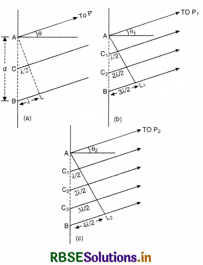
at angle θ2 given by
BL2 = d sin θ2 = 2λ
or sin θ2 = \(\frac{2 \lambda}{d}\)
or θ2 = \(\frac{2 \lambda}{d}\) provided θ2 is small.
In general, the various minima occur if the path difference between extreme rays is even multiple of λ/2.
i.e., d sin θn = \(\frac{2 n \lambda}{2}\) = nλ
or sin θn = \(\frac{n \lambda}{d}\)
or \(\frac{x}{\mathrm{D}}=\theta_n=\frac{n \lambda}{d}\) (As θn is very small, sin θn = θn)
The intensity of central fringe is maximum whereas that of other fringes falls off rapidly in either direction from the centre of the fringe pattern.
(b) Width of central maxima is the distance between first secondary minimum on either side of central point in front of slit.
∴ d sin θ = 1λ for first secondary minima.
or sin θ = \(\frac{\lambda}{d}\)
If f is the focal length of the focussing lens (on screen side), held close to the slit, then D, the distance of slit from the screen is equal to f i.e., D = f
∴ sin θ ≈ θ = \(\frac{y}{f}=\frac{y}{D}\)
or \(\frac{y}{D}=\frac{\lambda}{d}\) or y = \(\frac{\mathrm{D} \lambda}{d}\)
Since θ is half the angular width of central maxima of single slit,
∴ Width of central maxima
= 2y = \(\frac{2 \mathrm{D} \lambda}{d}=\frac{2 f}{d}\) .............................(i)
Width of secondary maxima is the distance between nth and (n + 1)th maxima.
We know for a nth minima a sin θn = nλ
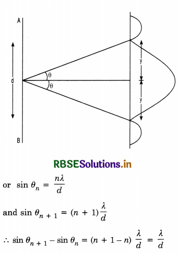
Since angles are small, sin θ = θ
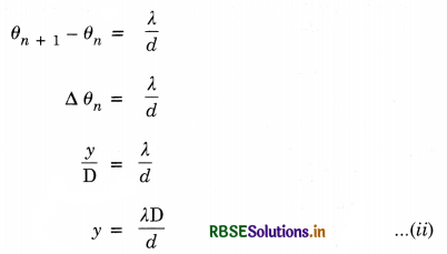
Thus we find that equation
- is twice the equation
- showing thereby that the central maxima is twice any secondary maxima.
If the width of slit is increased then as y decreases which shows that pattern will become narrower as the width of the slit is increased.

Question 14.
Distinguish between interference and diffraction.
Answer:
Differences between interference and diffraction
|
Interference |
Diffraction |
|
1. Interference takes place when light from two different wave-fronts coming from two coherent sources superimpose on each other. |
1. Diffraction is due to superposition of secondary wavelets from various points on the same wavefront. |
|
2. Bright fringes are of the same intensity. |
2. Intensity of secondary maximas goes on decreasing. |
|
3. Fringes are equispaced |
3. Fringes are not equispaced. |
|
4. Intensity of light is zero at minima. |
4. Intensity of light at minima is not zero. |
Question 15.
Explain resolving power of various optical instruments.
Answer:
Lens. The resolving power of a lens is its ability to resolve two points that are close to each other.
Eye. In case of the eye, two points can be seen distinctly if they subtend at the eye an angle equal to about one minute of arc. (This is on the assumption that the pupil of the eye is about 2 mm in diameter). The reciprocal of this angle is the resolving power.
Microscope, The limit of resolution of microscope is deter mined by the least distance between two point objects which can be distinguished. This distance d is given by
d = \(\frac{\lambda}{2 \mu \sin \theta}\)
where λ is the wavelength of light used to illuminate the object, θ is the half angle of the cone of light from the point object and µ the refractive index of the medium between the object and the objective (Fig. LAQ 15). For oil immersion objective microscopes, the resolving power is high. The expression µ sin θ is called numerical aperture, (for eye, µ sin θ = 0.004).
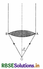
∴ Resolving power of microscope = \(\frac{1}{d}=\frac{2 \mu \sin \theta}{\lambda}\)
Telescope. The resolving power of a telescope is defined as the reciprocal of the smallest angular separation between two distant objects whose images are separated in the telescope. This is given by
dθ = \(\frac{1.22 \lambda}{a}\)
where λ is the wavelength of light, a is the diameter of the telescope objective and dθ = angle subtended by the point object at the objective.
∴ Resolving power of telescope
= \(\frac{1}{d \theta}=\frac{a}{1.22 \lambda}\)
To get a high resolving power, a telescope with large aperture objective has to be used or wavelength of light used should be small.

Question 16.
(a) Explain Polarisation. Explain the difference between polarised and unpolarised lights.
(b) What are plane of polarisation and plane of vibration?
Answer:
(a) Polarisation. The phenomenon of restricting the waves in oscillations to particular plane is called polarisation. A wave having oscillation in all possible directions is said to be unpolarised. When all the oscillations get confined along one direction, the wave is called plane polarised. The phenomenon of polarisation can be exhibited with a tourmaline crystal cut parallel to its crystallographic axes. Thus crystal has the property that it allows the vibrations parallel to its axis to pass through it.
Allow the unpolarised light to fall normally on the crystal T1. The outgoing light will be linearly polarised. The eye is incapable of detecting the polarisation of light, the emergent beam will appear only slightly coloured due to natural colour of the crystal if the crystal T1 is rotated about the ray as an axis, no change in intensity is observed. The crystal T1 acts as a polariser.
Place second similar crystal T2 behind T1 with its axis parallel to the axis to T1. If now the second crystal T2 is rotated about the ray as an axis the intensity of emergent beam is found to decrease gradually and finally no light emerges through T2 as shown in Fig. This will be so when the axis of two crystals are perpendicular to each other. In the Fig LAQ 16, crystal T1 cuts off vibration along x-axis, where the crystal T2 cuts off vibration along y-axis. This conclusively proves that light is a transverse wave, and this experiment demonstrates polarisation.
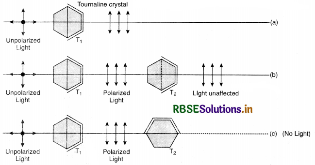
(b) An unpolarised light wave has vibrations in all planes. These vibrations can be resolved in two mutually perpendicular planes. One plane is parallel to plane of the paper and the other is perpendicular to it. Thus unpolarised light becomes equivalent to two perpendicularly polarised light. The molecules of the crystal point along a particular direction. The movement of the electrons produced by \(\vec{E}\) along this direction causes the electrons to absorb the radiation polarised in that direction. The radiation polarised in perpendicular direction is totally transmitted.
When radiations polarised by the polariser become incident on the analyser, only the cosine component of vibrations parallel to analyser axis pass through it. When analyser axis is parallel to polariser axis (i.e. angle between axes is zero) cosine component is full and complete vibrations pass. An analyser is rotated (i.e. angle is increased) component decreases and less vibrations pass. When analyser axis is perpendicular to polariser axis (crossed crystals) component becomes zero. Then no light passes.

Question 17.
(a) Explain polarisation by scattering and by reflection.
(b) State Brewster’s law connecting angle of polarization and refractive index. Prove that µ = tan ip.
Answer:
(a) Polarisation by scattering
The incident sunlight is unpolarised. The dots stand for polarisation perpendicular to the plane of the figure. The double arrows show polarisation in the plane of the paper. When this light becomes incident on nitrogen molecules of the atmosphere, electrons of the molecules are set into vibration in these two perpendicular directions and are accelerated.
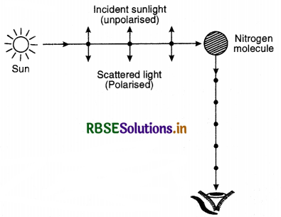
The observer is looking in a direction at 90° to the direction of sun. The electrons accelerating parallel to the double arrows do not radiate energy towards the observer. The electrons accelerating along dot radiate energy towards the observer. The radiation scattered towards the observer is therefore, represented by dots. The radiation is polarised perpendicular to the plane of the paper (Fig LAQ 17.39).
It is polarised perpendicular to the plane of the figure.
A plane at right angle to the plane of vibration of light wave is called plane of polarisation.
Polarised light by reflection. Fig shows unpolarised light, incident on a transparent (water) surface. The light is reflected as well as refracted. The angle of incidence is such that reflected light and refracted light proceed in perpendicular direction. It happens when i + r = 90°. In incident light, double arrows represent radiations polarised in plane of paper and dots represent radiations polarised perpendicular to the plane. In refracted wave, double arrows are parallel to the direction of reflected wave. These radiations are not transmitted alongwith the reflected light. It has only those radiations which are represented by dots. Hence reflected light becomes polarised perpendicular to the plane of the paper. The polarisation can be checked by an analyser.
(b) Brewster’s law. It state that the tangent of polarising angle is equal to the refractive index of transparent material.
i.e. tan ip = µ
or µ = tan ip
where ip is the polarising angle.
Proof. As shown in (Fig. LAQ 17 a) if ip is the angle of incidence (polarising angle) are r the corresponding angle of refraction, then according to
Brewster’s law.
∠POP' = 90°
∴ ip + r = 90°
or ip = 90° - r
or cos i = cos (90° - r) = sin r.
Now, if µ is the refractive index of the medium,
then
µ = \(\frac{\sin i_p}{\sin r}=\frac{\sin i_p}{\cos i_p}\)
Hence the tangent of the polarising angle is equal of the refractive index of the medium at which reflection takes place.
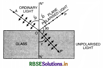
Question 18.
Show that at polarising angle, the reflected and refracted beams of light are at 90° to each other.
Answer:
Let µ be refractive index of the transparent surface. If ip is polarising angle and r is the angle of refraction as shown in Fig. (LAQ 17), then from Snell’ law, we have
µ = \(\frac{\sin i_p}{\sin r}\) .............................(1)
From Brewster’ law, we have
µ = tan ip = \(\frac{\sin i_p}{\cos i_p}\) ..........................(2)
From Eqs. (1) & (2), we have
\(\frac{\sin i_p}{\sin r}=\frac{\sin i_p}{\cos i_p}\)
or sin r = cos ip
or sin r = sin (90° - ip)
or r = 90° - ip
or ip + r = 90°
i.e. the reflected and refracted beams of light at polarising angle are perpendicular to each other.

Question 19.
State and explain Malus law.
Answer:
Malus law. It states that the intensity of polarised light transmitted through the analyser varies as the square of cosine of the angle between the plane of transmission of analyser and polariser. i.e. I ∝ cos2 θ
Proof
Let OQ = amplitude (\(\overrightarrow{\mathrm{A}}\)) of vibration of electric vector transmitted by the polariser.
θ = angle between the plane of analyser and polariser.
Let us resolve \(\overrightarrow{\mathrm{A}}\) into two components.
- A cos θ along OR (i.e. parallel to the plane of transmission of analyser).
- A sin θ along OP (i.e. perpendicular to the plane of transmission of analyser).
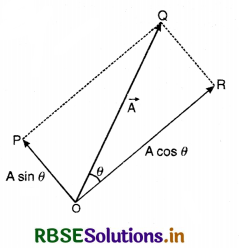
Since only A cos θ component is transmitted through the analyser, so the intensity of light transmitted through the analyser is given by:
I = (A cos θ)2
or I = A2 cos2 θ
or I = I0 cos2θ ......................(1)
where I0 = A2 is the intensity of incident light from the polariser.
So Eq. (1) can be written as I cos2θ.
Special cases
(i) When the plane of polariser and analyser are parallel to each other.
i.e. θ = 0°
From Eq. (1), we have
I = I0
i.e. maximum intensity.
(ii) When the plane of polariser and analyser are perpendicular to each other.
i.e. θ = 90°
From Eq. (1), we have I = 0
i.e. zero intensity.
Question 20.
(a) What are polaroids? Mention some of their practical uses.
(b) What is optical rotation? On what factors does it depend?
Answer:
(a) Polaroids. Tourmaline crystal is a natural polarising material and is a semi-precious gem and also not available in large size. Polaroids are artificially made large sheets or plates and capable of producing a strong beam of polarised light.
In 1852, W.B. Herpath observed that small needle-shaped crystals of quinine iodosulphate now called Harpathite have the property of polarising light. But the size of these crystals is so small that they cannot be used for large scale polarisation of light. In 1932, E.H. Land invented the technique of aligning the harpathite crystals as long chains parallel to each other. He arranged a large number of these crystals with their axis parallel to one another and placed in between the sheets of plastic. Such sheets act even more efficiently than the tourmaline crystals and are called sheet polarisers or polaroids.
Polaroids can also be obtained from a sheet of polyvinyl by stretching these sheets, the molecules become parallel to the direction of stress. The sheet is then impregnated with iodine. This is called H-polaroid. On heating H-polaroids in the presence of a dehydrating agent, it becomes strongly dichoric. This is called k-polaroid.
The Polaroid sheets have a characteristic plane called transmission plane. When the axis of these two planes are parallel to one another the light transmitted by first is also transmitted by second Fig., but if the planes are perpendicular to each other, then light transmitted by first is blocked by second [Fig. LAQ 20] and no fight comes out.
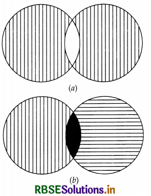
Uses. Following are practical uses of polaroids:
(1) In sun glasses. Sun glasses fitted with polaroids instead of coloured glasses are more efficient in protecting the eyes from glare due to reflected fight without obscuring details even in shadows.
(2) Wind shield of automobiles. Wind screen fitted with polaroid as well as head lights of automobiles protect the eyes of the drivers of the automobile from the dazzling fight of approaching vehicles. The transmission axes of the polaroids both in the head fights as well as the wind screen are oriented say at 45° with the vertical.
(3) In window panes. For this purpose, two Polaroid sheets are mounted one behind the other. On rotating one of the polaroid sheet, the amount of fight entering the room can be controlled. This is generally used in trains or aeroplanes etc.
(4) Three dimensional motion pictures. To make stereoscopic motion pictures, two pictures of the same scene are taken at slightly different angles. These two pictures are projected simultaneously on the screen but fight in two pictures is polarised at right angle to each other. The spectators view these pictures with the help of polaroid spectacles, to have three dimensional effect.
(b) Optical rotation (or optical activity)
The property of the substances to rotate the plane of vibration of incident plane polarised light is called optical activity and such substances are called optically active substances.
There are two types of such substances:
(i) Dextro rotatory or right handed
The substances that rotate the plane of vibration to the right i.e. in clockwise direction are called dextro-rotatory or right handed, e.g. cane sugar solution, NaCl etc.
(ii) Laevo rotatory or left handed
The substances that rotate the plane of vibration to the left i.e. in anticlockwise direction are called laevo-rotatory or left handed, e.g. fruit sugar solution, turpentine, nicotine etc.

Question 21.
In Young’s double slit experiment deduce the condition for (i) constructive and (ii) destructive interference at a point on the screen. Draw a graph showing variation of the resultant intensity in the interference pattern against position 'X' on the screen.
Answer:
Let S1, S2 be the two fine slits illuminated by a monochromatic source S of wavelength A.
Intensity of light at any point P on the screen at a distance D from the slit depends upon the path difference between S2P and S1P.
Let O be a point on the screen equidistant from S1 and S2, so path difference S1O and S2O is zero. Hence this point will have maximum intensity due to constructive interference and is called central fringe.
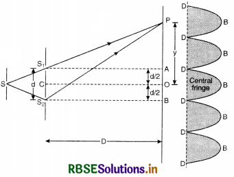
Let point P be lying on the screen at a distance y from O as shown in Fig. LAQ 10.
∴ Path difference between two waves reaching at P.
= S2P - S1P
In rt. ∠∆ S2BP, we have
(S2P)2 = (S2B)2 + (PB)2
or (S2P)2 = D2 + \(\left(y+\frac{d}{2}\right)^2\) ...........................(1)
In rt. ∠∆ S1AP, we have
(S1P)2 = (S1A)2 + (PA)2
or (S1P)2 = D2 + \(\left(y-\frac{d}{2}\right)^2\) ............................(2)
Subtracting Eq.(2) from Eq. (1), we get
(S2P)2 - (S1P)2 = \(\left(y+\frac{d}{2}\right)^2-\left(y-\frac{d}{2}\right)^2\)
or (S2P + S1P) (S2P - S1P) = 4y\(\frac{d}{2}\)
OR S2P - S1P = \(\frac{2 y d}{\mathrm{~S}_2 \mathrm{P}+\mathrm{S}_1 \mathrm{P}}\)
Since point P is very close to A and B
So S2P ≈ S1P ≈ D
∴ S2P - S1P = \(\frac{2 y d}{\mathrm{D}+\mathrm{D}}=\frac{y d}{\mathrm{D}}\)
∴ Path difference (S2P - S1P) = \(\frac{y d}{\mathrm{D}}\) ...........................(3)
(i) For construction interference [Bright Fringes]. For bright fringes, the path difference should be equal to integral multiple of d.
\(\frac{y d}{\mathrm{D}}\) = nλ
or y = n\(\frac{\lambda \mathrm{D}}{d}\)
If n = 0; y0 = 0, which is the position of central maxima.
If n = 1; y1 = \(\frac{\mathrm{D}}{d}\)λ, which is the position of first maxima.
If n = 2; y2 = \(\frac{2 \mathrm{D}}{d}\)λ, which is the position of 2nd maxima
Similarly, yn-1 = (n - 1) \(\frac{\mathrm{D}}{d}\)λ
and yn = n\(\frac{\mathrm{D}}{d}\)λ
Fringe width, ß = yn - yn-1
= \(\frac{\mathrm{D}}{d}\)y [n - (n - 1)]
ß = \(\frac{\mathrm{D}}{d}\)y ...............................(4)
(ii) For destructive interference [Dark Fringes]. For dark fringes, the path difference should be an odd multiple of λ/2.
\(\frac{\mathrm{D}}{d}\)y = (2n - 1) λ/2
or y = \(\frac{\mathrm{D}}{d}\) (2n - 1) \frac{\lambda}{2}
If n = 1; y1 = \(\frac{\mathrm{D}}{d} \frac{\lambda}{2}\), (which is the position of 1st minima.)
If n = 2; y2 = \(\frac{\mathrm{D}}{d} \frac{3 \lambda}{2}\), (which is the position of 2nd minima.)
If n = 3; y3 = \(\frac{\mathrm{D}}{d} \frac{5 \lambda}{2}\), (which is the position of 3rd minima.)
∴ Fringes width, ß = y3 - y2 = \(\frac{\mathrm{D}}{d}\) λ
or ß = \(\frac{\mathrm{D}}{d}\) λ ..............................(5)
From (4) and (5), we conclude that bright and dark fringes have equal fringe width
ß ∝ D
∝ λ
∝ \(\frac{1}{d}\)
If d = 0, ß = ∞ i.e. dark and bright bands will be infinitely well spaced and there will be uniform illumination.
Conclusions
- ß does not depend upon n so that all fringes have the same width.
- For fixed wavelength λ and separation d fringe width ß increases as D increases. Therefore, the dark fringes become darker and bright becomes less brighter. If D is very large, the two types of fringes become indistinguishable giving a sense of general illumination. Therefore, for good fringes the screen should not be too far off.
- For fixed D and λ, the fringe width ß is more if d decreases. This is why the two sources are kept very close for good fringes.
- Separation ∆ß between two adjacent bright or dark fringes subtend angle ∆θ at the centre O of the double slit
∆θ = \(\frac{\beta}{\mathrm{D}}=\frac{\lambda}{d}\)
The angular separation of fringes is given by \(\frac{\lambda}{d}\) and is independent of the position of the screen. It, therefore, gives a dirct way of measuring λ, the wavelength of light. - Interference pattern with white light. When slits are illuminated with white light, only central maxima is white (∵ at O, y = 0, n = 0 for all values of λ). All other bright lines become coloured. Coloured lines have their violet edges towards central maxima because y ∝ λ.
Note. For clear interference pattern, lines must be wide, for which d must be small. Hence the two coherent sources must be very close.

Question 22.
Describe the diffraction of light due to a single slit. Explain formation of a pattern of fringes obtained on the screen and plot showing the variation of intensity with angle θ in single slit diffraction.
Answer:
Huygens’ principle and the diagram for propagation of w avefront.
Assumptions on which Huygens’ principle is based are:
(i) The medium is homogeneous.
(ii) The medium is isotropic.
Huygens’ principle
(a) Each point of a wavelength becomes a source of new disturbance called the secondary wavelets which travel in all directions with the same speed provided the medium remains the same.
(b) The secondary wavefront is the tangent plane joining all the wavefronts.
Fig. SAQ 1 (a) represents the trace of secondary wavefront at a certain instant and Fig. SAQ 1 (b) represents the trace when the light has travelled a large distance.
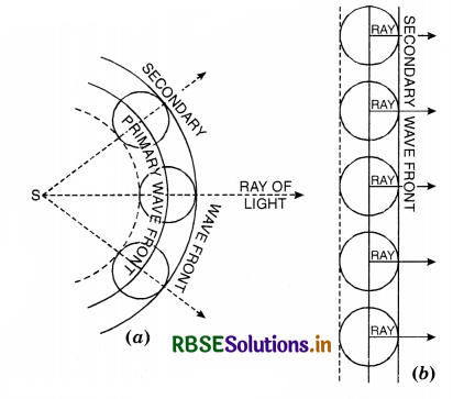
Rays of light are perpendicular to the wavefront.
(a) Diffraction of light by narrow slit
Consider a narrow slit AB perpendicular to plane of paper on which a monochromatic light be incident normally. Due to diffraction pattern consists of a central band much wider than the slit width just opposite to the slit and bordered on either side by dark and bright fringes of decreasing intensity. It is found that
- the intensity of the secondary maxima goes on decreasing.
- the width of central maximum is double that of a secondary maximum.
Consider a plane wavefront WW incident on the slit AB (Fig. LAQ 13). Imagine the slit to be divided into a large number of very narrow strips of equal width parallel to the slit. When the wavefront reaches the slit, each narrow strip parallel to the slit can be considered to be a source of Huygens’ secondary wavelets.
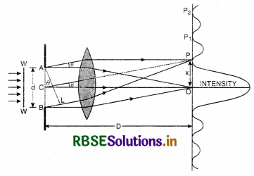
Central Maxima. Let us first consider the effect of all the wavelets at the point O just opposite to the middle of the slit. Since distance between the slit and the screen is very large as compared wdth the width of the slit, the wavelets cover the same distance and reach O in the same phase. Thus the wavelets reinforce each other’s effect to give maximum intensity at O.
Position of secondary minima
Let us now consider the intensity at a point P above O produced by the rays travelling at an ∠θ with the original direction. Since the width of the slit is very small, all the rays reaching P proceed almost parallel to each other. The wavelets from all the points in the slit start in the same phase but as they travel different distances, they reach P in different phases. Draw AL normal to BP.
The path difference between the extreme rays is BP - AP = BL.
Let C be the mid-point of slit or path difference between AP and CP = \(\frac{\lambda}{2}\)
∴ Wavelets starting from A and C shall reach the point P in opposite phases and cancel each other’s effect.
Similarly, the wavelets from a strip below A are cancelled by the wavelets from a corresponding strip below C.
In ∆ ABL,
\(\frac{\mathrm{BL}}{\mathrm{AB}}\) = sin θ
∴ BL = AB sin θ
or BL = d sin θ
For first minima, BL = λ;
∴ d sin θ = λ
or sin θ = \(\frac{\lambda}{d}\)
Since θ is small ∴ sin θ = θ = \(\frac{x}{\mathrm{D}}\)
\(\frac{x}{\mathrm{D}}\) = θ = \(\frac{\lambda}{d}\) or x = \(\frac{\mathrm{D}}{d}\) λ
At a point slightly above P i.e. at P1, the path difference between the two rays in BL1.
Position of secondary maxima
If BL1 = \(\frac{3}{2}\)λ then slit AB can be divided into three equal parts Fig. LAQ 13 (b). The waves from corresponding points AC1 and C1C2 cancel each other. The waves from C2B produce first secondary maximum at an angle θ1 given by
d sin θ1 = \(\frac{3}{2}\) λ
sin θ1 = \(\frac{3}{2} \frac{\lambda}{d} \)
If θ1 is small then sin θ1 = θ1
It another point P2, (Fig. LAQ 13 (c)), the path difference between two rays is BL2 = 2λ, then, the slit AB can be supposed to be divided into four equal parts. The waves from corresponding points of the parts AC1 and C1C3 cancel each other. Also the waves from the corresponding points C2C3 and C3B cancel each other producing second minima
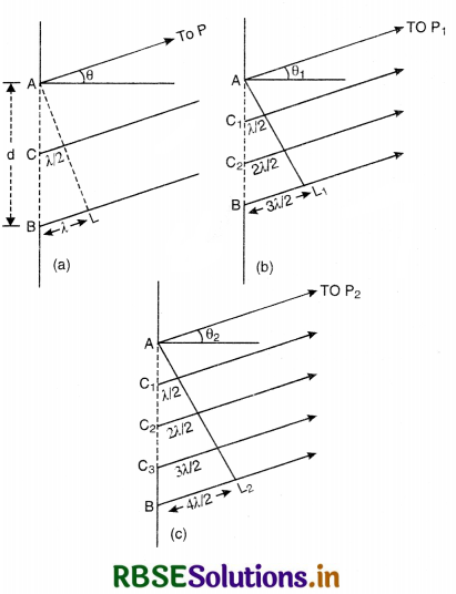
at angle θ2 given by
BL2 = d sin θ2 = 2λ
or sin θ2 = \(\frac{2 \lambda}{d}\)
or θ2 = \(\frac{2 \lambda}{d}\) provided θ2 is small.
In general, the various minima occur if the path difference between extreme rays is even multiple of λ/2.
i.e., d sin θn = \(\frac{2 n \lambda}{2}\) = nλ
or sin θn = \(\frac{n \lambda}{d}\)
or \(\frac{x}{\mathrm{D}}=\theta_n=\frac{n \lambda}{d}\) (As θn is very small, sin θn = θn)
The intensity of central fringe is maximum whereas that of other fringes falls off rapidly in either direction from the centre of the fringe pattern.
(b) Width of central maxima is the distance between first secondary minimum on either side of central point in front of slit.
∴ d sin θ = 1λ for first secondary minima.
or sin θ = \(\frac{\lambda}{d}\)
If f is the focal length of the focussing lens (on-screen side), held close to the slit, then D, the distance of slit from the screen is equal to f i.e., D = f
∴ sin θ ≈ θ = \(\frac{y}{f}=\frac{y}{D}\)
or \(\frac{y}{D}=\frac{\lambda}{d}\) or y = \(\frac{\mathrm{D} \lambda}{d}\)
Since θ is half the angular width of central maxima of single slit,
∴ Width of central maxima
= 2y = \(\frac{2 \mathrm{D} \lambda}{d}=\frac{2 f}{d}\) .............................(i)
Width of secondary maxima is the distance between nth and (n + 1)th maxima.
We know for a nth minima a sin θn = nλ
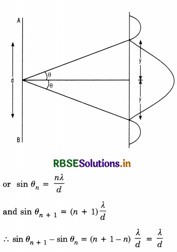
Since angles are small, sin θ = θ
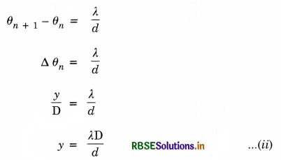
Thus we find that equation
- is twice the equation
- showing thereby that the central maxima is twice any secondary maxima.
If the width of slit is increased then as y decreases which shows that pattern will become narrower as the width of the slit is increased.

Question 23.
How is a wavefront defined? Distinguish between a plane wavefront and a spherical wavefront. Using Huygens’ principle draw a figure showing the propagation of a plane wave refracting at a plane surface separating two media. Hence verify Snell’s law of refraction.
Or
State Huygens’ pricniple with the help of a suitable diagram. Verify Snell’s law of refraction using Huygens’ wave theory. Explain the refraction of a plane wavefront incident on a plane surface.
Answer:
Wavefront. Wavefront is defined as the locus of the neighbouring particles of the medium which are in the same phase of disturbance.
The line along which energy is propagated is called a ray. It is ⊥ wavefront at any point. In Fig. LAQ 1 (a) the concentric spheres represent spherical wavefronts with the source of light at O.
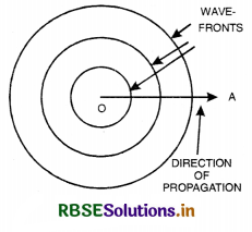
Types of wavefront
1. Spherical wavefront. A wavefront due to point source in a three dimensional isotropic space is called spherical wavefront.
Consider a point source of light placed in an isotropic medium i.e., a medium in which the velocity of light is the same in all directions. The disturbance from the point source travels equally in all directions.
If c = velocity of light, then after time t. light will have travelled a distance equal to ct in all directions. The locus of all points where light reaches after time t will be a sphere. A set of spherical wavefront represents a diverging beam of light [Fig. LAQ 1 (b)]
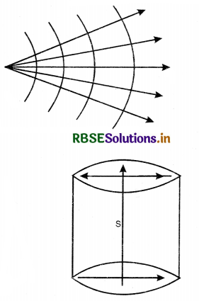
2. Cylindrical wavefront. When the slit is a source of light, all points equidistant from the source lie, on a cylinder. Therefore, wavefront is cylindrical [Fig. LAQ 1 (c)].
3. Plane wavefront. When the source is at infinite distance, the radius of curvature of wavefront will be very large.
A small portion of spherical wavefront with source at infinite distance is a plane wavefront. [Fig. LAQ 1 (d)].
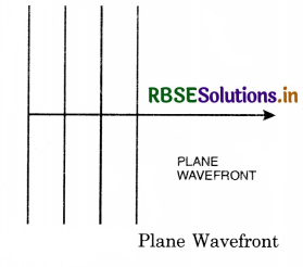
Huygens’ Principle
It is based on the following two assumptions:
(1) All the particles on a given wavefront (Called primary wavefront) can be regarded as point sources of new disturbance called the secondary wavelets which travel out with the same velocity as that of the original waves, provided the medium is the same.
(2) A surface tangential to the secondary wavelets gives the position and shape of the new wavefront.
Illustration. Consider O to be a point source of light and WW a spherical wavefront originating from it (Fig. LAQ 2 (a)) All the points a, b, c,... on this will be vibrating in unison and may be regarded as sources of secondary disturbances. To find the position of the wavefront after an interval t second, draw spheres of radius ct (where c is the velocity of light) with a, b, c,... as centre which wall be Huygens' secondary waves. These waves touch a sphere W'W' whose centre is at O. The spherical surface constitutes the new secondary wavefront which is also spherical.
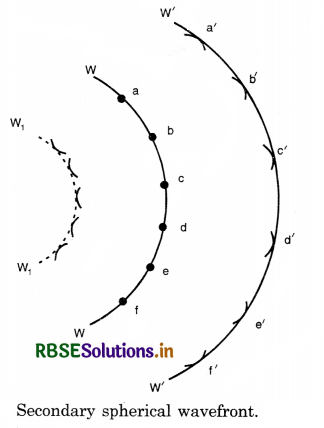
If the source of light is at a large distance, we will have a plane wavefront as shown in Fig. LAQ 2 (b).
Referring again to Fig. LAQ 2 (a), it will be seen that the secondary wavelets spread out in the backward direction also, and W1W1 represents the envelope of these back portions of the waves by dotted lines. Thus W1W1 is also a secondary wavefront which in reality does not exist. To account for this difficulty, it is assumed that the only effective part of the secondary wavelets is the portion which lies on the forward secondary wavefront. The remaining part of the secondary wavelet is ineffective. Thus, there are no back waves and the wavefront W1W1 is absent.
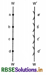
(a) Let XY be a plane refracting surface separating rarer medium I of refractive index µ1, from denser medium II of refractive index µ2 [µ2 > µ1], then
\(\frac{\mu_2}{\mu_1}=1 \mu_2=\frac{v_1}{v_2}\)
Where v1 is the velocity of light in medium I and v2 is the velocity of light in medium II.
According to Huygens’ principle, every point on incident wavefront AB is a source of secondary wavelets. By the time wavelet from point B reaches at point C, the wavelet from point A would have reached at point D s.t. time taken from B to C is equal to time taken from A to D.
i.e. t = \(\frac{\mathrm{BC}}{v_1}=\frac{\mathrm{AD}}{v_2}\)
\(\frac{\mathrm{BC}}{\mathrm{AD}}=\frac{v_1}{v_2}\) ..........................(i)
First law of refraction
In rt. ∠∆ ABC,
\(\frac{\mathrm{BC}}{\mathrm{AC}}\) = sin i
or BC = AC sin i ........................(ii)
Similarly, in rt. ∠∆ ADC,
\(\frac{\mathrm{AD}}{\mathrm{AC}}\) = sin r
or AD = AC sin r .......................(iii)
From (ii) and (iii), we have
\(\frac{\mathrm{BC}}{\mathrm{AD}}=\frac{\sin i}{\sin r}\)
From (i) and (iii), we have
\(\frac{\sin i}{\sin r}=\frac{v_1}{v_2}\) = 1µ2
This is first law of refraction and is called Snell’s law.
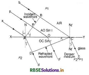
Second law of refraction. Since incident ray, refracted ray and the normal, all lie on the same plane XY at the point of incidence. This proves second law of refraction.
(b) Behaviour of wavefront while passing through:
(i) Prism
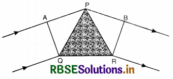
Consider a small angled prism PQR and a plane wavefront AQ incident on the prism. The course of rays is as shown is Fig. (b). According to Huygens’ principle, every point on wavefront AQ is the source of secondary wavelets. The secondary wavelets from Q travel through the material of the prism and the secondary wavelets from A travel almost in air, and the other wavelets travel different thicknesses of the glass prism. Since the speed of light in glass is less than the speed of light in air thus the ray of light bends towards the base after passing through the prism.
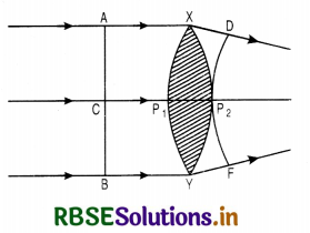
(ii) Lens
Consider a convex lens XY as shown in Fig. LAQ 4 (c) and a plane wavefront AB incident on it. The course of rays is as shown in the figure. According to Huygens’ principle, every point on wavefront AB is the source of secondary wavelets. The secondary wavelets from A or B travel almost through air and the secondary wavelets from C travel a distance P1P2 almost inside the material of the lens. Since speed of fight in glass is less than the speed of fight in air. Thus the rays of fight takes the form of spherical wave form DP2F.

Question 24.
Derive an expression for fringe width in a two slit interference experiment.
Answer:
Let S1, S2 be the two fine slits illuminated by a monochromatic source S of wavelength A.
Intensity of light at any point P on the screen at a distance D from the slit depends upon the path difference between S2P and S1P.
Let O be a point on the screen equidistant from S1 and S2, so path difference S1O and S2O is zero. Hence this point will have maximum intensity due to constructive interference and is called central fringe.
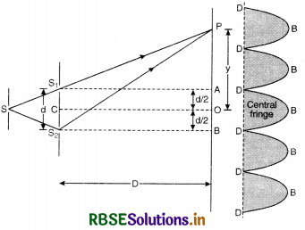
Let point P be lying on the screen at a distance y from O as shown in Fig. LAQ 10.
∴ Path difference between two waves reaching at P.
= S2P - S1P
In rt. ∠∆ S2BP, we have
(S2P)2 = (S2B)2 + (PB)2
or (S2P)2 = D2 + \(\left(y+\frac{d}{2}\right)^2\) ...........................(1)
In rt. ∠∆ S1AP, we have
(S1P)2 = (S1A)2 + (PA)2
or (S1P)2 = D2 + \(\left(y-\frac{d}{2}\right)^2\) ............................(2)
Subtracting Eq.(2) from Eq. (1), we get
(S2P)2 - (S1P)2 = \(\left(y+\frac{d}{2}\right)^2-\left(y-\frac{d}{2}\right)^2\)
or (S2P + S1P) (S2P - S1P) = 4y\(\frac{d}{2}\)
OR S2P - S1P = \(\frac{2 y d}{\mathrm{~S}_2 \mathrm{P}+\mathrm{S}_1 \mathrm{P}}\)
Since point P is very close to A and B
So S2P ≈ S1P ≈ D
∴ S2P - S1P = \(\frac{2 y d}{\mathrm{D}+\mathrm{D}}=\frac{y d}{\mathrm{D}}\)
∴ Path difference (S2P - S1P) = \(\frac{y d}{\mathrm{D}}\) ...........................(3)
(i) For construction interference [Bright Fringes]. For bright fringes, the path difference should be equal to integral multiple of d.
\(\frac{y d}{\mathrm{D}}\) = nλ
or y = n\(\frac{\lambda \mathrm{D}}{d}\)
If n = 0; y0 = 0, which is the position of central maxima.
If n = 1; y1 = \(\frac{\mathrm{D}}{d}\)λ, which is the position of first maxima.
If n = 2; y2 = \(\frac{2 \mathrm{D}}{d}\)λ, which is the position of 2nd maxima
Similarly, yn-1 = (n - 1) \(\frac{\mathrm{D}}{d}\)λ
and yn = n\(\frac{\mathrm{D}}{d}\)λ
Fringe width, ß = yn - yn-1
= \(\frac{\mathrm{D}}{d}\)y [n - (n - 1)]
ß = \(\frac{\mathrm{D}}{d}\)y ...............................(4)
(ii) For destructive interference [Dark Fringes]. For dark fringes, the path difference should be an odd multiple of λ/2.
\(\frac{\mathrm{D}}{d}\)y = (2n - 1) λ/2
or y = \(\frac{\mathrm{D}}{d}\) (2n - 1) \(\frac{\lambda}{2}\)
If n = 1; y1 = \(\frac{\mathrm{D}}{d} \frac{\lambda}{2}\), (which is the position of 1st minima.)
If n = 2; y2 = \(\frac{\mathrm{D}}{d} \frac{3 \lambda}{2}\), (which is the position of 2nd minima.)
If n = 3; y3 = \(\frac{\mathrm{D}}{d} \frac{5 \lambda}{2}\), (which is the position of 3rd minima.)
∴ Fringes width, ß = y3 - y2 = \(\frac{\mathrm{D}}{d}\) λ
or ß = \(\frac{\mathrm{D}}{d}\) λ ..............................(5)
From (4) and (5), we conclude that bright and dark fringes have equal fringe width
ß ∝ D
∝ λ
∝ \(\frac{1}{d}\)
If d = 0, ß = ∞ i.e. dark and bright bands will be infinitely well spaced and there will be uniform illumination.
Conclusions
- ß does not depend upon n so that all fringes have the same width.
- For fixed wavelength λ and separation d fringe width ß increases as D increases. Therefore, the dark fringes become darker and bright becomes less brighter. If D is very large, the two types of fringes become indistinguishable giving a sense of general illumination. Therefore, for good fringes the screen should not be too far off.
- For fixed D and λ, the fringe width ß is more if d decreases. This is why the two sources are kept very close for good fringes.
- Separation ∆ß between two adjacent bright or dark fringes subtend angle ∆θ at the centre O of the double slit
∆θ = \(\frac{\beta}{\mathrm{D}}=\frac{\lambda}{d}\)
The angular separation of fringes is given by \(\frac{\lambda}{d}\) and is independent of the position of the screen. It, therefore, gives a dirct way of measuring λ, the wavelength of light. - Interference pattern with white light. When slits are illuminated with white light, only central maxima is white (∵ at O, y = 0, n = 0 for all values of λ). All other bright lines become coloured. Coloured lines have their violet edges towards central maxima because y ∝ λ.
Note. For clear interference pattern, lines must be wide, for which d must be small. Hence the two coherent sources must be very close.

Question 25.
What is interference of light? Write two essential conditions for sustained interference pattern to be produced on the screen.
Draw a graph showing the variation of intensity verses the position on the screen in Young’s experiment, when
(a) both the slits are opened
(b) one of the slits is closed.
What is the effect on interference pattern in Young’s double slit experiment when
(i) screen is moved closer to the plane of slits?
(ii) separation between two slits is increased. Explain your answer in each case.
Answer:
Interference of Light. The phenomenon of redistribution of energy in a medium due to superimposition of waves from two coherent sources of light is called Interference of Light.
Constructive Interference. At points, where the crest of one wave falls on the crest of the other or a trough of one falls on the trough of the other, the amplitude of the resulting wave becomes maximum. Hence the energy or the intensity of light at such points becomes maximum. This is called Constructive Interference.
Destructive Interference. At some other points where the trough of one falls on the crest of the other or crest of one falls on the trough of the other, the amplitude of the resulting waves becomes minimum. Hence the energy or intensity becomes minimum. This is called Destructive Interference.
Law of conservation of energy is obeyed. It should be clearly understood that in interference of light no light energy is destroyed. The loss of energy at the points of destructive interference appears as the increase of energy at the points of constructive interference.
Conditions for sustained interference. To produce sustained (or stationary) interference following conditions should be fulfilled:
- Two sources must be coherent, so the sources emit continuous waves of the same wavelength (or frequency) which are either in the same phase or a constant phase difference.
- The waves should be preferably of the same amplitude to get complete darkness in case of destructive interference.
- Two sources must be very close to each other, if it is not so, the path difference at particular point of observation will be large and the maximas will be very close to each other and may overlap.
(∵ ß ∝ \(\frac{1}{(\text { distance between the sources) }}\)) - Two sources must be very narrow, a broad source of light is equivalent to a large number of narrow sources and each set of two sources will give its own interference pattern and their overlap will result in general illumination.
- The distance between two sources and the screen should be large, so that the dark and bright fringes are of large width [∵ ß ∝ D (distance between two sources and screen)].
Graphs
(a) When both the slits are opened See Fig. LAQ 11.
(b) When one of the slits is closed
The graph is shown in Fig. 11 for S1 or S2.
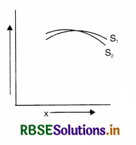
Since fringe width, ß = \frac{\lambda \mathrm{D}}{d}
So (i) when screen is moved closer to the plane of slits, D decreases and hence ß will also decrease.
(ii) When separation between the slits is increased, d increases and hence ß will decrease.

Question 26.
What are coherent sources of light? Draw the variation of intensity with position in the interference pattern of Young’s double slit experiment.
Answer:
Coherent sources. Coherent sources are those sources which emit continuously light of the same wavelength and magnitude either in the same phase or with a constant phase difference.
Expression
Let the waves of two coherent sources be
y1 = a sin ωt
and y2 = b sin (ωt + Φ),
where a and b are the respective amplitudes of the two waves and Φ is the constant phase angle by which the second wave leads the first wave [Fig].
According to superposition principle, the displacement y of resultant wave is
y = y1 + y2 = a sin ωt + b sin (ωt + Φ)
or y = a sin ωt + b sin ωt cos Φ + b cos ωt sin Φ
or y = sin ωt (a + b cos Φ) + cos ωt. b sin Φ
Substituting a + b cos Φ = A cos θ ......................(1)
and b sin Φ = A sin θ ....................(2)
we have
y = sin ωt. A cos θ + cos ωt. A sin θ
or y = A [sin ωt. cos θ + cos ωt. sin θ]
or y = A sin (ωt + θ),
where A is the amplitude of the resultant wave. Squaring and adding (1) and (2), we have
a2 + b2 cos2 Φ + 2ab cos Φ + b2 sin2 Φ
= A2 cos2 θ + A2 sin2 θ
or a2 + b2 (cos2 Φ + sin2 Φ + 2ab cos θ)
= A2 (cos2 θ + sin2 θ)
or A2 = a2 + b2 + 2ab cos Φ
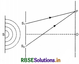
Since resultant intensity is proportional to square of amplitude,
∴ I ∝ A2
or I ∝ (a2 + b2 + 2ab cos Φ)
or I = a2 + b2 + 2 ab cos Φ ........................(3)
(For convenience, we assume that intensity of light is equal to square of amplitude)
(i) For constructive interference (or for maximum).
I should be maximum
i.e. cos Φ = 1 and Imax = (a + b)2
or Φ = 0, 2π, 4π, ..........................
or Φ = 2π n (where n = 0, 1, 2, ......................)
or Path diff. = \(\frac{\lambda}{2 \pi}\)Φ = \(\frac{\lambda}{2 \pi}\) 2πn = n λ ...........................(4)
So, for constructive interference (or for maximum intensity), path difference should be integral multiple of λ.
(ii) For destructive interference (or for minima)
I should be minimum
i.e. cos Φ = -1 and Imin = (a - b)2
or Φ = π, 3π, 5π, ..........................
or Φ = (2n + 1) π (where n = 0, 1, 2, ......................)
or path difference = \(\frac{\lambda}{2 \pi}\) (2n + 1) π
= (2n + 1) \(\frac{\lambda}{2}\) .........................(5)
So, for destructive interference (or for minimum intensity), path difference should be an odd multiple of λ/2.
Variation of intensity with position
From above discussion, we find that intensity of light is maximum when path difference is nλ i.e. ±λ, 2λ, 3λ ............... and minimum when path difference is (2 n+ 1) λ/2
i.e. ± \(\frac{\lambda}{2}\), 3\(\frac{\lambda}{2}\), 5\(\frac{\lambda}{2}\) ...................
The variation in intensity of light with position in interference is as shown in Fig. LAQ 9 (b).
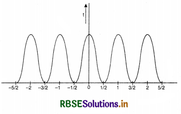

Question 27.
(a) Define a wavefront. Using Huygen’s principle, verify the laws of reflection at a plane surface.
(b) In a single slit diffraction experiment, the width of the slit is made double the original width. How does this effect the size and intensity of the central differaction band? Explain.
(c) When a tiny circular obstacle is placed in the path of light from a distant source, a bright spot is seen at the centre of the obstacle. Explain why.
Answer:
(a) Wavefront is the locus of the particles of the medium in same vibrating phase.
Laws of reflection at a plane surface
Let XY be a plane reflecting surface and AB be a plane wavefront incident on the surface as shown in Fig. LAQ 3.
According to Huygens’ principle, every point on wavefront AB is a source of secondary wavelets and the time during which wavelet from B reaches at C, the reflected wavelet from A would arrive at D.
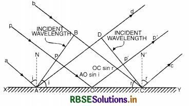
If t is the time taken by wavelet from B to C [or A to D] then
t = \(\frac{\mathrm{BC}}{v}=\frac{\mathrm{AD}}{v}\)
or BC = AD ......................(i)
First law of reflection.
In rt. ∠∆ ABC,
\(\frac{\mathrm{BC}}{\mathrm{AC}}\) = sin i
or BC = AC sin i ........................(ii)
In rt. ∠∆ ADC,
\(\frac{\mathrm{AD}}{\mathrm{AC}}\) = sin r
or AD = AC sin r .......................(iii)
Putting Eq. (ii) and (iii) in Eq. (i), we get
AC sin i = AC sin r
or sin i = sin r
or i = r
i.e. Angle of incidence = Angle of reflection.
This proves first law of reflection.
Second law of reflection
Since incident ray, reflected ray and the normal all lie on the same plane i.e. plane XY, so second law of reflection is also proved.
(b) Size of diffraction pattern
y0 = 2\(\frac{\lambda \mathrm{D}}{d}\)
When the slit is made double the original width i.e. d = 2d
y = \(\frac{2 \lambda \mathrm{D}}{2 d}=\frac{1}{2}\left(\frac{2 \lambda \mathrm{D}}{d}\right)=\frac{y_0}{2}\)
Hence the area of the central diffraction pattern becomes \(\frac{1}{4}\). So, the intensity of central diffraction pattern becomes 4-times.
(c) When circular obstacle is placed in the path of light as shown in the given figure, then the waves get different from the edges of the circular obstacle and interfere constructively at the centre and hence a bright spot is seen at the centre.

HOTS QUESTIONS
Question 1.
In a two-slit experiment with monochromatic light, fringes are obtained on the screen placed at some distance from the slits. If the screen is moved by 5 x 10⁻² m towards the slits, the change in fringe width is 3 x 10⁻⁵ m. If the distance between the slits is 10-3 m, calculate the wavelength of the light used.
Answer:
Fringe width ß = \(\frac{\lambda \mathrm{D}}{d}\) (Here λ and d is fixed)
The change in fringe width due to change in D is:
∆ß = ∆D\(\frac{\lambda}{d}\)
or λ = \(\frac{\Delta \beta . d}{\Delta \mathrm{D}}\)
Given ∆D = 5 x 10⁻² m (decrease), ∆ß = 3 x 10⁻⁵ m, d = 10-3 m
∴ λ = \(\frac{3 \times 10^{-5} \times 10^{-3}}{5 \times 10^{-2}}\)
= 6 x 10⁻⁷ m = 6000Å

Question 2.
A double slit apparatus is immersed in a liquid of refractive index 1.33. It has slit separation of 1mm and distance between the plane of slits and screen is 1.33 m. The slits are illuminated by a parallel beam of light whose wavelength in air is 6300Å
(i) Calculate the fringe width.
(ii) One of the slits of the apparatus is covered with a thin glass sheet of refractive index 1.53. Find the smallest thickness of the sheet to bring the adjacent minimum on the axis.
Answer:
Here µ1 = 1.33, d = 1 mm = 10-3 m, D = 1.33 m, λ = 6300Å = 6.3 x 10⁻⁷ m
When the apparatus is immersed in the liquid λ
changes to λ' = \(\frac{\lambda}{\mu_l}\)
(i) Fringe width
ß = \(\frac{\lambda^{\prime} \mathrm{D}}{d}=\frac{\lambda \mathrm{D}}{\mu_l d}\)
= \(\frac{6.33 \times 10^{-7} \times 1.33}{1.33 \times 10^{-3}}\)
or ß = 6.3 x 10⁻⁴ m = 0.63 m
(ii) Displacement of fringes
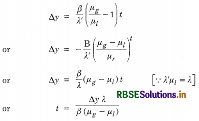
But, we know that ∆y is the separation between adjacent dark and bright fringe
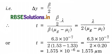
Question 3.
A beam of light of wavelength 600 nm from a distant source falls on a single slit 1.00 mm wide and the resulting diffraction pattern is observed on a screen 2m away. What is the distance between the first dark fringes on either side of the central fringe?
Answer:
Position of minima due to diffraction at a single slit is given by
a sin θ = nλ
∴ sin θ = \(\frac{n \lambda}{a}=\frac{1 \times 600 \times 10^{-9}}{1.0 \times 10^{-3}}\)
= 6 x 10⁻⁴ m
For small θ, sin θ ≃ θ = 6 x 10⁻⁴ radian
Let y be the distance of first minima on either side of central maxima, then
θ = \(\frac{y}{D}\)
or y = θD = 6 x 10-4 x 2 = 12 x 10-4 m
So, the distance between first dark fringes on either side of central maxima is
2y = 2 x 12 x 10-4 = 24 x 10-4 m = 2.4 mm
Question 4.
You have learnt in the text how Huygens’ principle leads to laws of reflection and refraction. Use the same principle to deduce directly that a point object placed in front of a plane mirror produces a virtual image whose distance from the mirror is equal to the object distance from the mirror.
Answer:
To prove, let us take the point object on the centre and draw a circle so that it touches the mirror. We can consider it as the plane section of the spherical wavefront from the point object that has just touched the mirror. Now again draw the position of the same wavefront after certain time say t in the presence and in the absence of the plane mirror. Hence we obtain two symmetrically located arcs on either side of the mirror. Then we can easily find using simple geometry that the image of the object (i.e. centre of reflected wavefront), lies at the same distance from the mirror as the object is situated from the mirror.

Question 5.
A polariser and an analyser are oriented so that maximum light is transmitted. What is the fraction of the maximum light transmitted when analyser is rutated through (i) 30° and (ii) 60°?
Answer:
From Malus law, we have
I = I0 cos2 θ
(i) For θ = 30°
I = I0 cos2 30° = I0 (\(\frac{\sqrt{3}}{2}\))2 = \(\frac{{3}}{4}\)I0
∴ \(\frac{\mathrm{I}}{\mathrm{I}_0}=\frac{3}{4}\) = 0.75
(ii) For θ = 60°
I = I0 cos2 60° = I0 (\(\frac{1}{2}\))2 = \(\frac{\mathrm{I}_0}{4}\)
∴ \(\frac{\mathrm{I}}{\mathrm{I}_0}=\frac{1}{4}\) = 0.25
